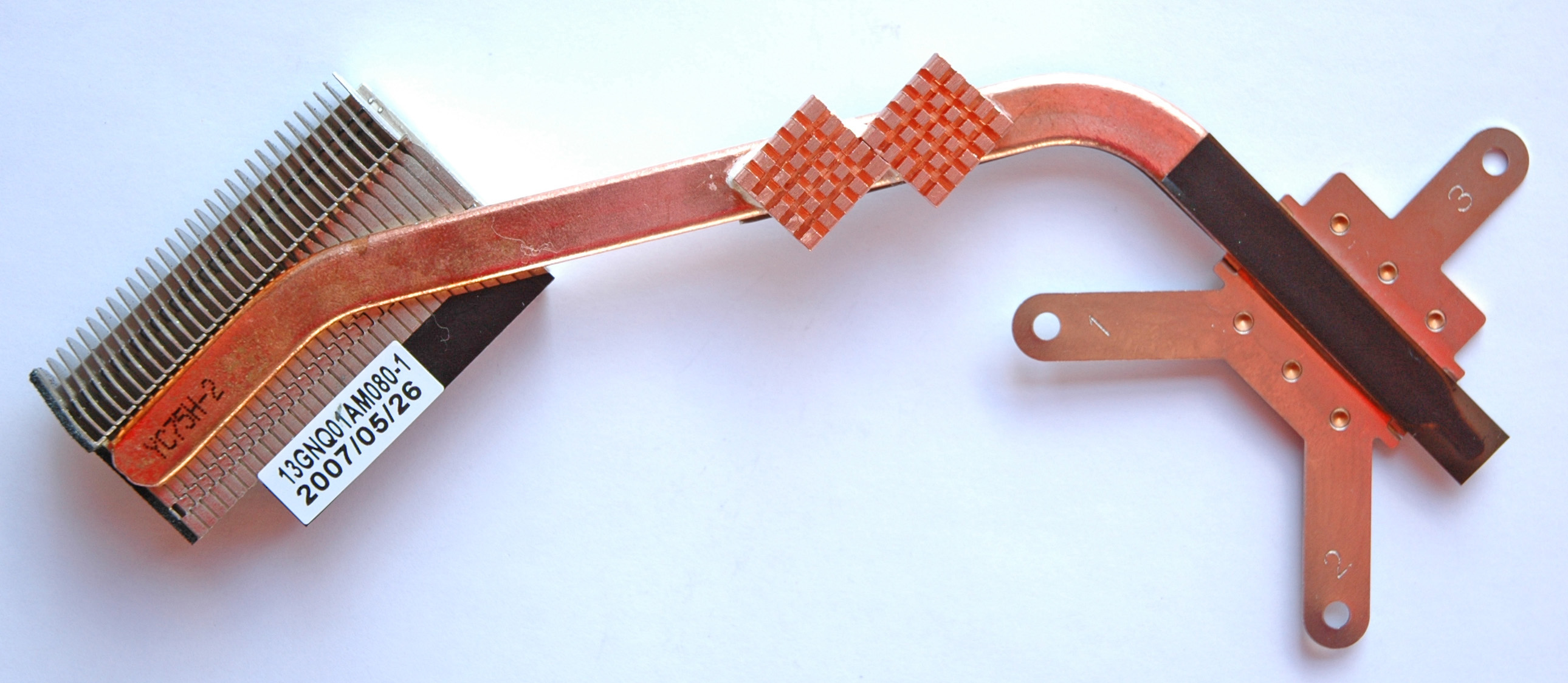
15. Video Heatsink “ASME” 1.0 (the BEST in the world)
Please, Don’t Rush! Use safety glasses!
Try to sense and imagine the decision before its implementation. Untraditional thinking and ideas are extremely valuable for me.
Question: “Who’s the best designer (engineer) in the world?”I would be happy if you achieve better results than me. You have this potential and I’m sure that you can!
Tip: Before VGA mounting replace the thermal compound of the North Bridge and do the respective mod. See the “North Bridge Heatsink”
Step #1: Make the Heatsink “ASME”
Tip: With this song the things will be easily done – “Absolute Beginners”, David Bowie
There are two ways to make the Heatsink “ASME” – “Professional” and “Do It Yourself”.
The first one is the best one! Find out in your area some small workshop with CNC machines. Then give to that business all files from chapter “VGA Heatsink Drafts” in section “Drafts / Manufacturer or Workshop”. You are done, and ready for the next step - the Assembly!
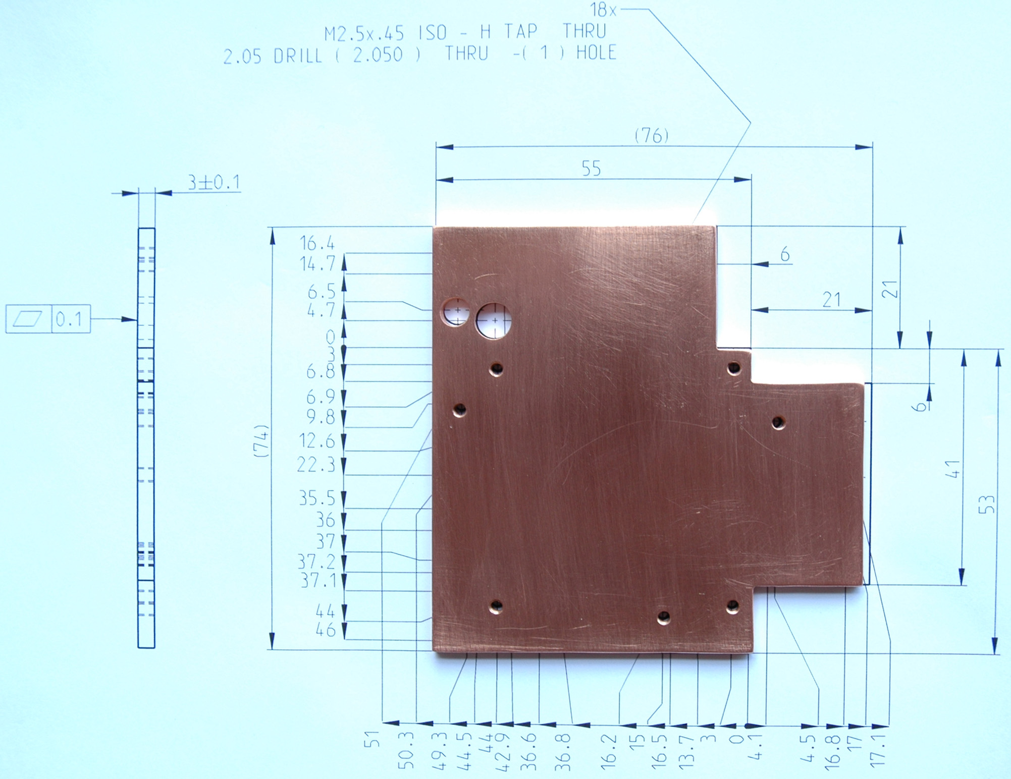
If you choose to “Do It Yourself” then the drafts from chapter “VGA Heatsink Drafts” in section “Models / Do It Yourself” are for you. We will follow the next steps:
1) Print it without shrink or zooming
2) Stick the model to a copper sheet
3) Mark all points
4) Cut & Drill without any measuring
5) You have the perfect heatsink
6) Repeat the same for the GPU<=>CPU bridge parts
7) VGA Thermal Module Assy - AssemblyIf you can’t to do this you steel have the option to take the “Professional” way. If that is a problem for you too, then don’t waste your time and buy another system! I wish you good luck and all the best! Thanks for your attention!
Print it without shrink or zooming. Instructions how to print the model:
Tip: Use Quality Laser Paper 28lb / 105gr/m1) Download & Open pdf’s files Heatsink or Heatsink’s Outline (“Models / Do It Yourself”)
2) Print without shrink or zooming (Page Scaling: None)3) Make sure that your print is correct, check the distance between holes 1-2-3-4 (Heatsink’s Outline Model), must be exactly 41 mm.
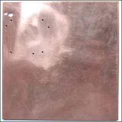
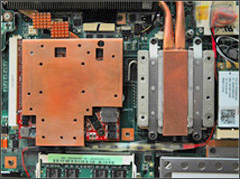
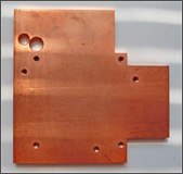
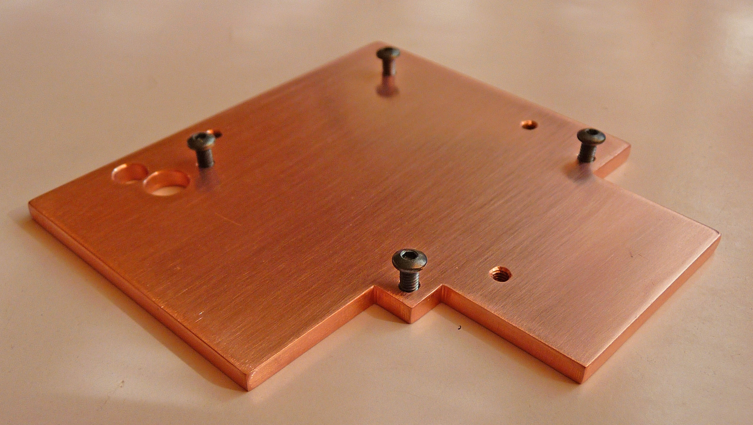
4) After you have all heatsink’s details from a paper you can put them on your system for a check.Stick the model to a copper sheet. From the printed page cut the model via outlines. Use a glue to stick it on the corresponding copper sheet (watch the thickness, in this case 3mm). Here I'm using a Copper Sheet 6” x 6” enough exactly for 4 video heatsinks. Here you are pictures with the Entire Plate & Close Views.
The “ASME” Model is stick to a Copper Sheet 6” x 6”

Mark all points. Use the center punch and hummer to mark all the holes.
Cut & Drill without any measuring (or Drill & Cut what you preffer).
- Use safety glasses!
- Use a “Drill 2.05 (.0807")” in “Hex-Shank Drill Chuck” (from chapter “Hardware Tools”) to drill all holes
- Make the threads with a “Tap M2.5 x .45 mm” in “Tap Wrench T-Handle Style, 0 - 1/4" (1.6-6.3mm)”
- Drill the holes A & B (the hole B is ATI's related) too with their respective drills
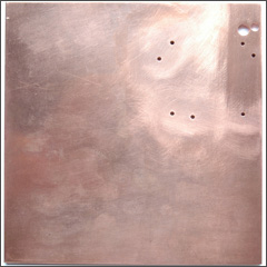
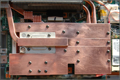
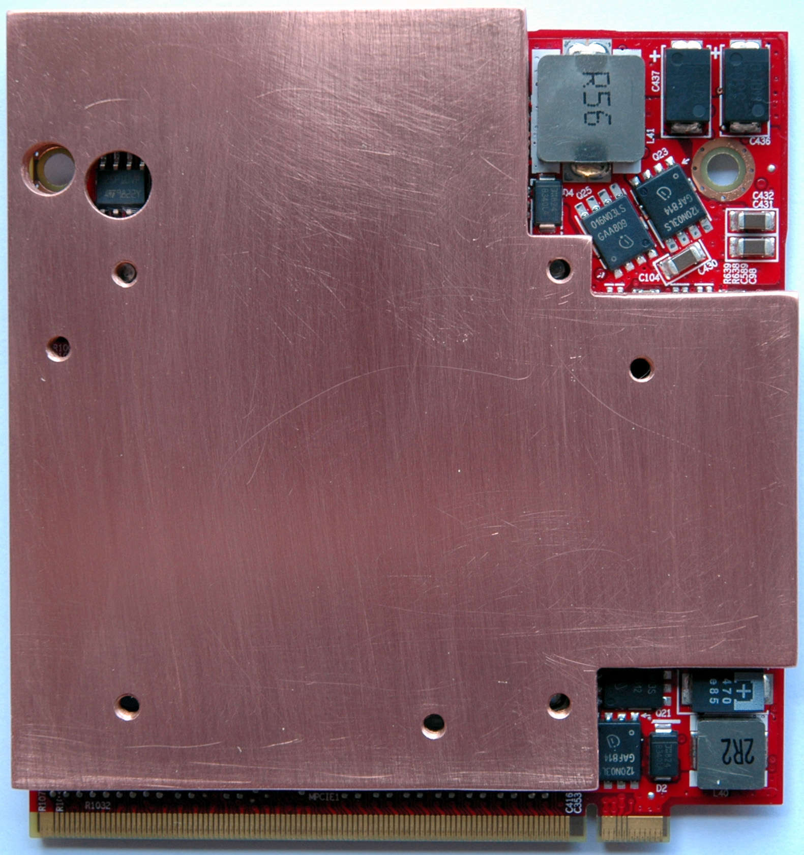
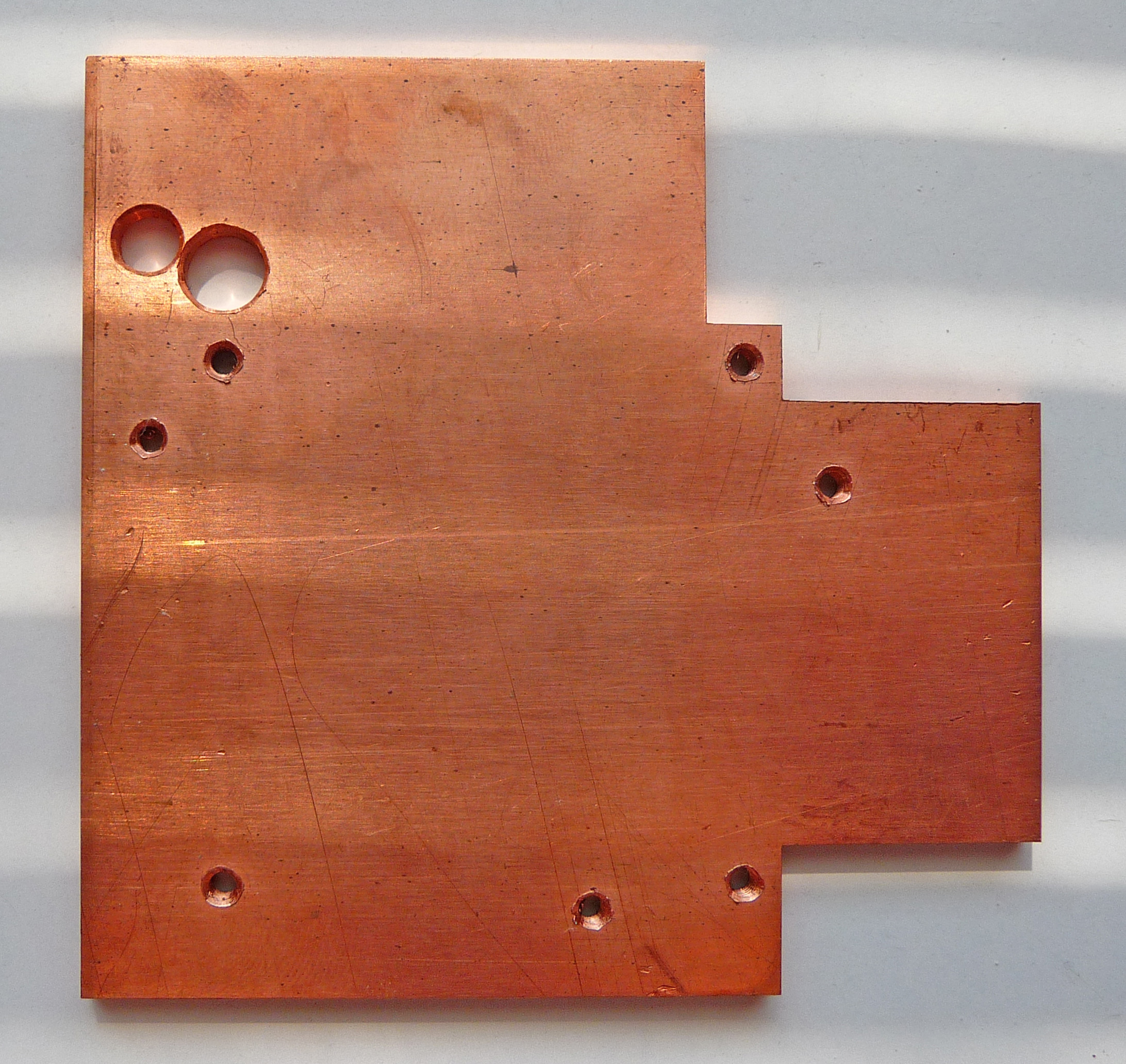
Drilled Plate Front
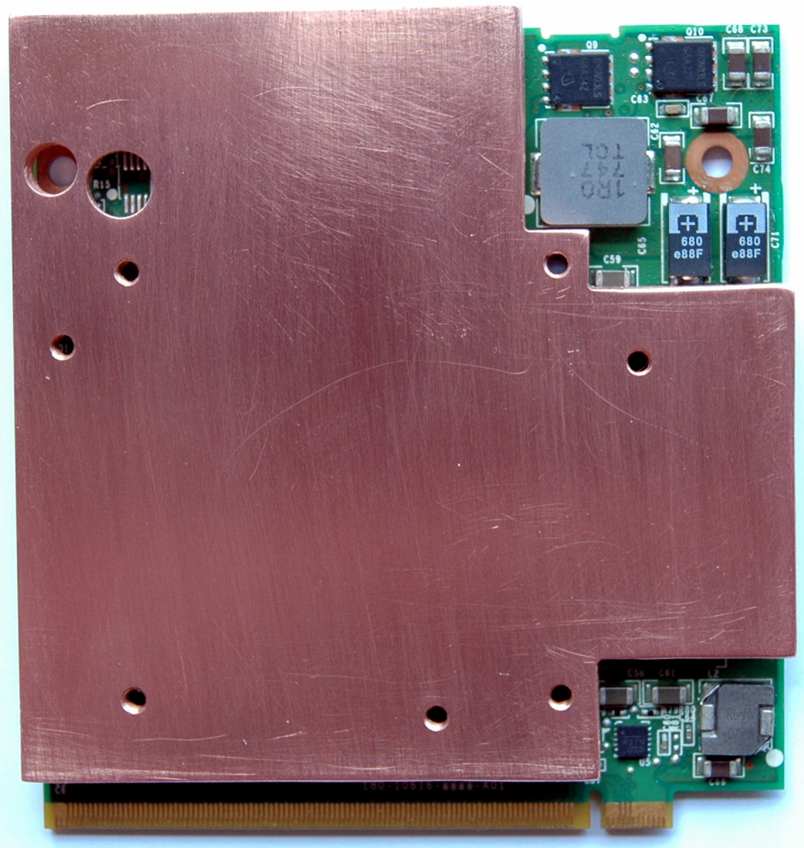
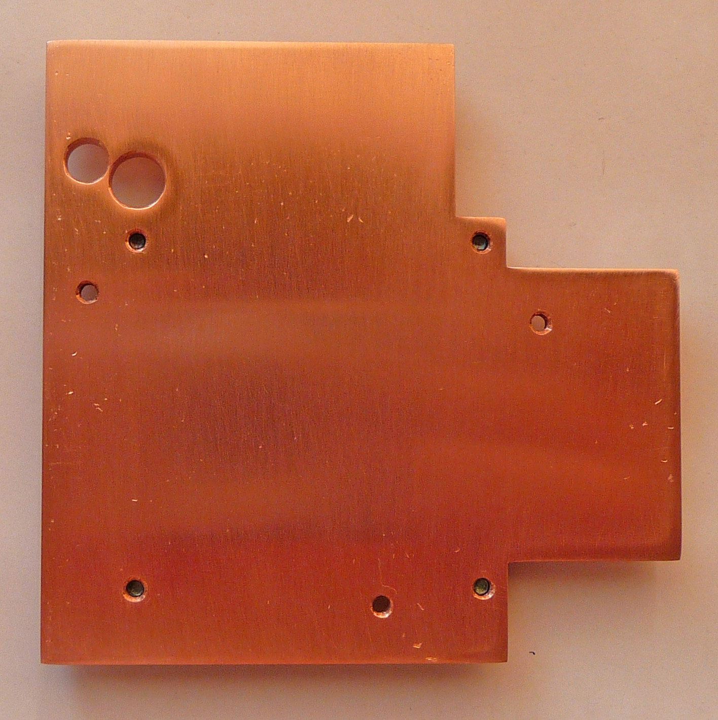
Drilled Plate Back
- Use a hacksaw to cut the heatsink
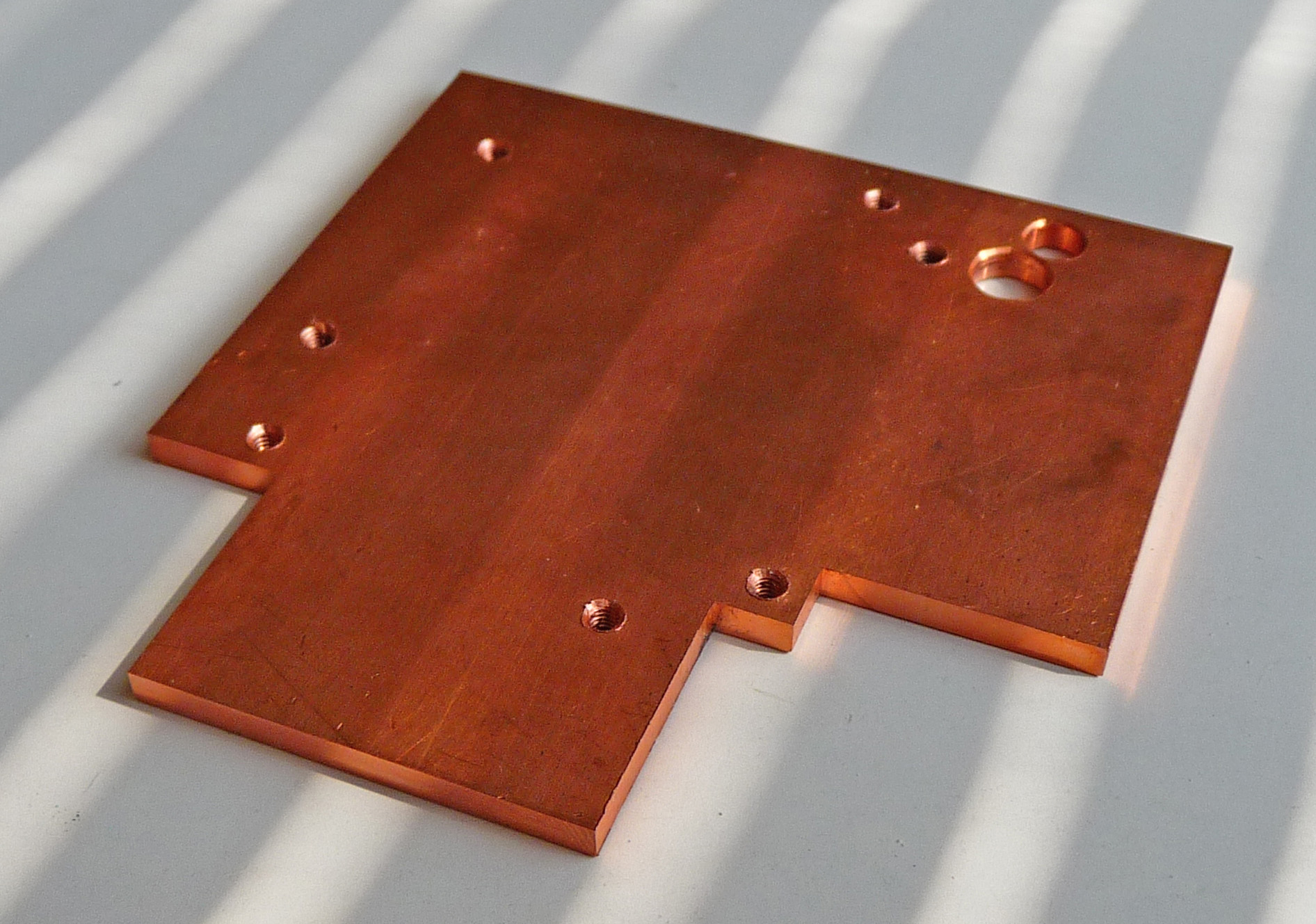
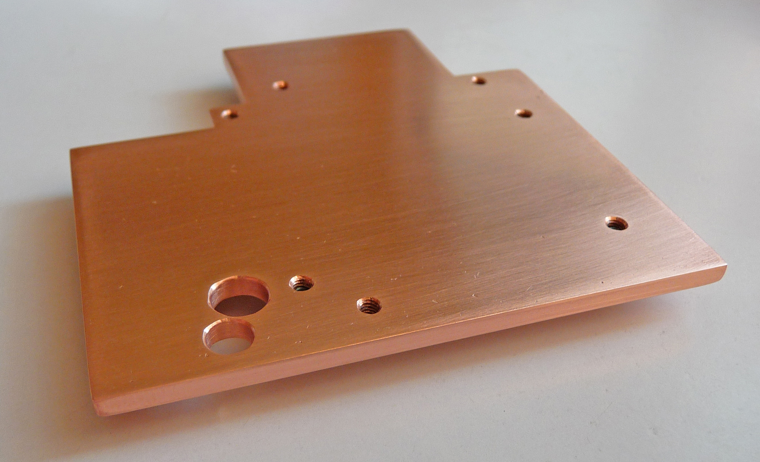
Of course the best way when we are using Copper Sheet 6” x 6” is first to make the holes & threads and then to cut. It's not wrong if you cut and then finish with the rest. It's up to you. On the next pictures you can see two shapshots before the final stage:

- Clean the edges slowly and carefully with “Standard Diamond Hand File, Flat, Medium (120) Grit, 0.25" Width”
- For finishing use a Sandpaper Sheet “Fine/180” or finest one (it’s better)
- Screw and unscrew 3 times in every hole a new screw fully to check and clean the threads
- Use a vacuum cleaner to clean the heatsink and the work space
Here it is the final view of the video heatsink
You have the perfect heatsink. Use a tooth brush and tooth paste for final cleaning of the heatsink. Now wash it with worm water and left it to dry.
Repeat the same for the GPU<=>CPU bridge parts. Don’t forget to clean carefully every detail!
Now your parts must look better than mine because I have a prototype. Here you are the pictures of the prototype parts:
VGA Thermal Module Assy - Assembly. The detail “GPU<=>CPU Strip2” consists of molded “VGA Thermal Module Assy” and Strip #2. Cleanse very carefully the surfaces with “Isopropyl Alcohol”. To stick these two parts together use the thermal adhesive “Arctic Alumina Premium Ceramic Thermal Adhesive”. Follow the product directions and use “Spring Clamps”.
Here you are the pictures of the VGA Assy:
Pictures of the Assembled Heatsink “ASME”:


Step #2: Attach the Heatsink “ASME” to the VGA
For this purpose we will follow the next steps (don’t forget to use safety glasses):
1) Make Copper Pads GDDR
2) Make ATI Spacers (Aluminum)
3) Testing & Adjustment
4) Attach the Heatsink “ASME” to the VGAMake Copper Pads GDDR. The pad’s size is (14.5 x 11 x 0.8~0.78). Use a hacksaw to cut 4 pads from a copper sheet with thickness 0.8 mm. I have two “ATI Mobility Radeon HD 3650 512MB DDR2” and the thickness of copper’s memory pads is different for every one of them. The reason for that is called tolerance. Every component (PCB, GPU, Memory chips. heatsink) and process (wave solder process, our actions) they have its own tolerances. That’s why I used for memory pads two copper’s sheets with thicknesses 1/32” (0.79375 mm) and 0.032” (0.8128 mm). In my case I filed 0.005 mm ~ 0.010 mm. Most manufacturers are using regular thermal pads because it’s fast and easy way to deal with the tolerances.
Tip: If you need to file use a sandpaper sheet “Fine/180”. Put the sandpaper over a smooth and flat surface. Then gently slide back and forth the copper’s pad with a finger over it. After every 10~15 moves, check the thickness with a caliper.
Make ATI Spacers (Aluminum). The spacer specification and link are on chapter “Hardware Tools”. There isn’t a spacer with height 1.7 mm. That’s why we’ll file the spacers (2 mm) to 1.7 mm with “Standard Diamond Hand File, Flat, Medium (120) Grit, 0.25" Width”. After every 10~15 file’s moves, check the height with a caliper. Spacers with 1.7 mm are fit perfect on my two ATI's VGA.
For “NVidia 9600M GT 512M DDR3” you'll need spacers (3 mm). The height is between 2.2~2.5 mm. You must find out yourself the exact height.
It’s possible to use washers as spacers if you are extremely careful and precise. I’m not recommending this approach! For me it was a raw way to determine spacer’s height.
Washers as Spacers (not recommended):
Testing & Adjustment. Here is the one of the biggest secret of our success. At this stage we have:
- 4x spacers (ATI’s 1.7 mm)
- 4x “Copper Pads GDDR”
- 4x “Socket Cap Screw M2.5 x 6 mm”
- 1x “Hex L-Key 1.5 mm”
- 4x “Flat Washers M2.7”
- 1x Heatsink “ASME”
We will follow the next steps:
1) Check & Adjust Spacer’s Height
2) Check & Adjust Copper Pads GDDR Thickness
Check & Adjust Spacer’s Height. Cover VGA heatsink’s mounting holes from both sides with “Super-Slick Teflon PTFE Tape” as is on the next two pictures. Then use something sharp to drill a hole (1.5~2 mm) in the tape (a big needle or punch). One of the washer’s sides is with sharp edges while another has well rounded slick edges. Take the screw and put it into a washer (sharp edges are directed to the screw’s head, see the pictures). Then gently start to screw the screw with the washer into the tape’s hole from VGA back side. When finish with all 4 screws and washers turn back the VGA and put spacers over the screws.
Take the heatsink “ASME” and VGA with one hand and with the “Hex L-Key 1.5 mm” in another start to screw with one rotation every screw one by one (screw 1 one rotation => screw 2 one rotation => screw 3 one rotation => screw 4 one rotation and do it again from the beginning until finish with very gentle force). Don’t rush and be careful here is no need from force. The good result is when GPU crystal is touching entirely the heatsink! That is the key to good thermal conductivity between GPU and heatsink which we’ll make perfect at the next step with "Noctua NT-H1".
In a case where GPU in not fully touch heatsink you will need to file their respective spacer(s) until achieve full touch (contact). Don’t try to correct the situation with stronger fastening - "That Is Wrong"! Don’t forget to fasten very gently!
VGA Back (screw+washer+tape+vga) & Front Sites(spacer+tape+vga+screw) pictures:
Check & Adjust Copper Pads GDDR Thickness:
1) Put a drop of thermal compound on all 4 memory chips
2) Firmly press copper’s memory pads over the chips
3) Attach the heatsink “ASME” to the video card
4) With a tooth stick try to push every pad gently. If someone of them slips freely then you needed more thickness
5) Check that GPU’s crystal is still touching entirely the heatsink. If not, then you need to file more copper’s memory pad(s). After that, repeat the procedure from the beginning. Remove previous compound with “Isopropyl Alcohol”
Attach the Heatsink “ASME” to the VGA.
Tip: Use the Magic – “Cat People (Putting Out Fire)”, David Bowie“Cleaning! Cleaning! Cleaning!”. That’s the biggest secret for the heat transfer between GPU crystal and any heatsink.
Clean carefully your work place, remove any dust around you. Use a tooth brush and tooth paste for final cleaning of the heatsink “ASME” and the “Copper Pads GDDR”. Now wash all with worm water and left them to dry. Your hands must be clean too. Use vacuum cleaner for the VGA. Don’t touch with the plastic intake the PCB or its parts! Use “Cotton Swabs” with “Isopropyl Alcohol” to clean GDDR chips and GPU crystal. Repeat the procedure for the GPU in this way – use first wet (Isopropyl Alcohol) and immediately after that dry cotton swab to clean the GPU crystal. Do the same for the center of heatsink “ASME”. Both of them must be extremely clean without a speck of dust, greasy spots, greasiness and residue. Don’t touch them with fingers!Now Follow the Final Steps:
It’s a time for a test drive. Start the engine and watch on your windshield for some POST messages or something else. If that is the case then you are ready to install the video drivers. Go to the section “Upgrade VGA Drivers” and install them. Check the temperatures, make some tests, ,…, and return to the section “Mount the GPU<=>CPU Bridge”.
- Put a drop of thermal compound on all 4 memory chips
- Firmly press copper’s memory pads over the chips
- Clean carefully top sides of the copper memory pads as already you know and wait 60 seconds
- Put a drop of thermal compound on all 4 copper memory pads
- Take a look at GPU crystal. If you decide cleanse it again
- Put a drop of thermal compound on the GPU crystal. On this stage the picture must look at like this:
- Attach the heatsink to the video card. Follow the procedure from “Check & Adjust Spacer’s Height”. Don’t forget to fasten very gently!
- Inspect very carefully the VGA with mounted heatsink “ASME”
- Clean the VGA with a vacuum cleaner
- Inspect it again very carefully from all sides. With a tooth stick push every spacer gently. If someone of them moves then gently fasten the respective screw(s). In front of you are the next heatsink pictures of the prototype that is properly attached to the video card:
- Clean the VGA’s MXM II Slot and around with the vacuum cleaner
- You are ready to mount the VGA in our C90S. Do It!
- Attach the “VGA Assy” with 1x Original M2.5 x 3 and 4x M2.5 x 3 screws. Don’t forget that all 14 screws from GPU side are M2.5 x 3 mm! It's very important! Remember that!
If you can’t see anything on the screen then turns off the system. Please, do the next:
1) Remove PSU & Battery
2) Remove video adapter and carefully inspect both the MXM slot & the VGA pins. Clean the pins with “Isopropyl Alcohol” and wait 1-2 minutes. Clean around the heatsink with a vacuum cleaner too
3) Then assemble things again and try to start the systemIf your system is still not working then something is wrong with the VGA. Try to check it again (including disassembling of the heatsink). You have to find out where is the problem!


Step #3: Mount the GPU<=>CPU Bridge
For this purpose we will follow the next steps:
1) CPU Thermal Module Assy Mod
2) Mount the GPU<=>CPU Bridge
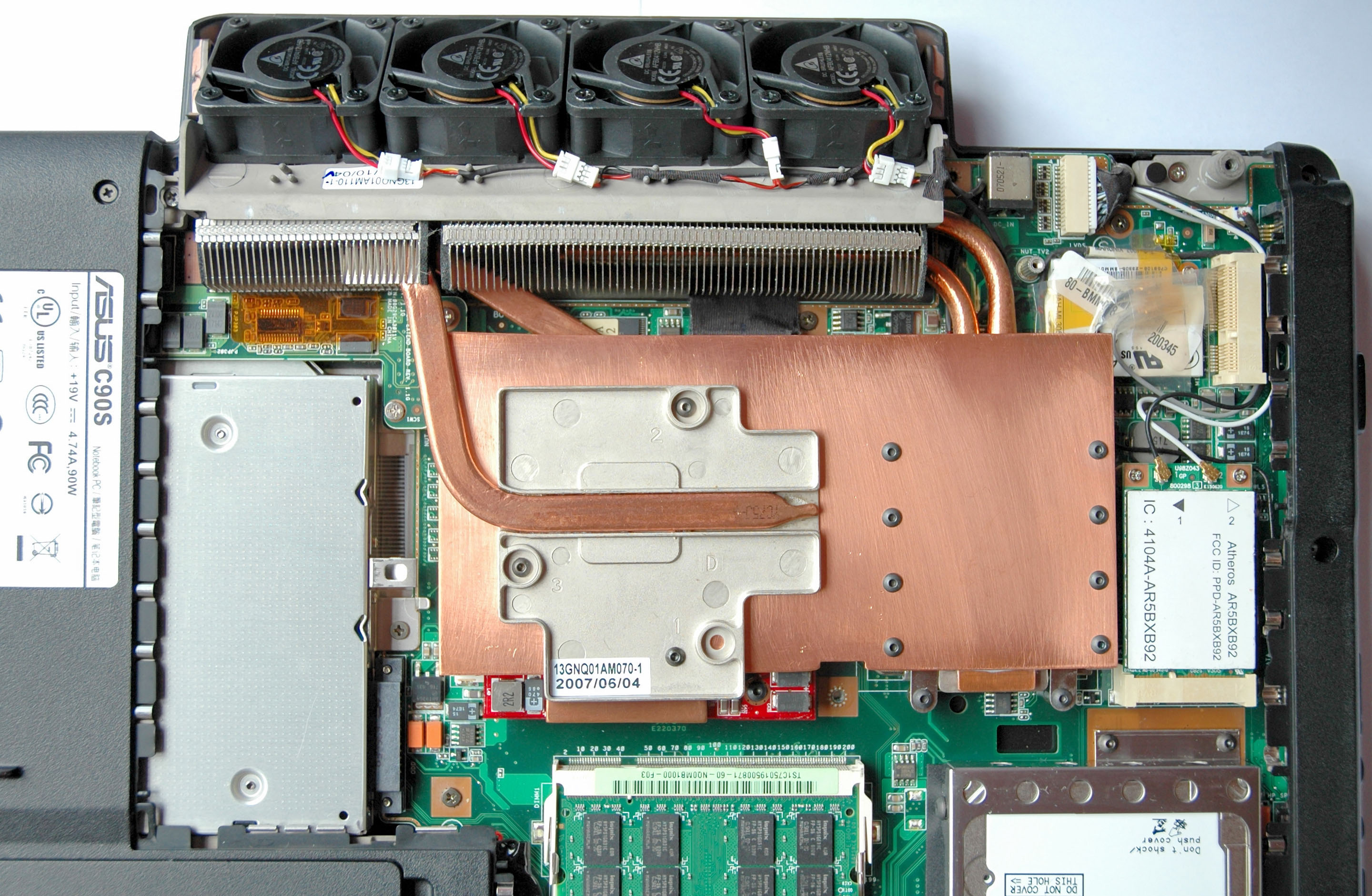
CPU Thermal Module Assy Mod. Make the 5 screws on Strip #2 a little loose, in that way we can move the strip back and forth. The movement is around a half millimeter. Attach another 2 Strips (#1 & #3) in the same way as Strip #1. Arrange (justify) the strips from the right CPU side. When they are in the line, fasten the screws gently. Use a pencil to mark the centers of the 8 holes on the “CPU Thermal Module Assy”. Then remove the Strips and “CPU Thermal Module Assy”.
Don’t forget to use safety glasses! Put the “CPU Thermal Module Assy” on smooth and flat surface. Be careful for the heatsink and copper pipe! Use gently a hummer with the center punch to mark the holes, because the material is very soft. Use a “Drill 2.05 (.0807")” in “Hex-Shank Drill Chuck” (from chapter “Hardware Tools”) to drill slowly all holes. Then make the threads with a “Tap M2.5 x .45 mm” in “Tap Wrench T-Handle Style, 0 - 1/4" (1.6-6.3mm)”. Screw and unscrew 3 times in every hole a new “M2.5 x 6 mm” screw fully to check and clean the threads. Use a vacuum cleaner to clean the “CPU Thermal Module Assy” and the work space.
Cleanse very carefully the surfaces (the two CPU’s copper pipes & CPU’s Rising Strip) with “Isopropyl Alcohol”. To stick these two parts together use the thermal adhesive “Arctic Alumina Premium Ceramic Thermal Adhesive”. Follow the product directions and use “Spring Clamps”. Here you are a picture:
Cleanse the CPU and “CPU Thermal Module Assy” with “Isopropyl Alcohol”. Then use a thermal compound and mount the “CPU Thermal Module Assy”.
Mount the GPU<=>CPU Bridge. Attach the Strips and fasten the screws in next order:
1) GPU Side
2) CPU Side
3) Fasten the ScrewsGPU Side:
Tip: Don’t forget that all 14 screws from GPU side are M2.5 x 3! It's very important! Remember that!
- “VGA Assy” namely Strip #2 with 4x M2.5 x 3 screws and 1x Original M2.5 x 3, loosely
- Strip #1 with 3x M2.5 x 3 screws, loosely
- Strip #3 with 6x M2.5 x 3 screws, loosely
CPU Side:
Tip: Don’t forget that all 8 screws from CPU side are M2.5 x 6! It's very important! Remember that!
- Strip #1 with 2x M2.5 x 6 screws, loosely
- Strip #2 with 2x M2.5 x 6 screws, loosely
- Strip #3 with 4x M2.5 x 6 screws, loosely
Fasten the Screws. After Strips alignment, fasten gently all screws. Your final view must be better than mine picture:
Important Options:
1) When finish all mods use a very small part of "Noctua NT-H1" over GPU Heatsink & CPU Rising Strip before attaching the strips for better thermal conductivity and easy disassembling next. If you put too much thermal compound then disassembling will be difficult! In that case try to slide (move) back and forth the strip(s) before removing.
2) Use "Loctite 243 Threadlocker" to prevent our fasteners from looseningNow you own the best heatsink “ASME” in the world. You did it yourself!
I'm waiting from you world records. Do it!History
Here you are some pictures of GPU heatsink with HD3650, GPU & CPU Rising Strips & Before them:


Step #4: Upgrade VGA Drivers
My choice for VGA is “ATI Mobility Radeon HD 3650 512M DDR2” (378 Million Transistors & 55nm Technology). I'm using XP 32-bits with SP3 and ATI’s video driver “ATI Mobility HD 3650 Drivers 9.10” for XP 32-bits. You must install Video & HDMI drivers. Here you are the installation's steps:
1) Download "ATI Mobility HD 3650 Drivers 8.6 & 9.10 for XP 32-bits"
2) Extract the archive with the drivers
3) Install Video: run the file “ATI Mobility HD 3650 Drivers 8.6 & 9.10 for XP 32-bits\9-10\Driver\setup.exe”
4) Install HDMI: run the file “ATI Mobility HD 3650 Drivers 8.6 & 9.10 for XP 32-bits\9-10 HDMI Audio\setup.exe”
5) After a correct installation your “Device Manager” must be clean from warnings. Check it!If you have different OS download the last driver’s versions from ATI's web site. After that unlock driver support for HD3650 Mobility with the tool "Mobility Modder 1.2.1.0", which modify some .inf files and you are ready to install it.
Question: "Why we need to unlock driver support for HD3650 Mobility"?For those of you with another VGA look at manufacturer’s WEB site for drivers.
16. Video Heatsink “ASME” 4.0
The exploration and development of an effective cooling solution pass thru different stages and ideas. I came to the conclusion that “ASME” 4.0 is the perfect base for a start with its simplicity and the opportunity for further customizations. The revision 4.0 is easy to be built and it’s the recommended way for you.
The main difference between the two revisions is that in rev. 4.0 the strip between the GPU & CPU is only one with metric dimensions 152x76x0.8 (exactly the half of a copper sheet 6” x 6” with the same thickness) and that the GPU heatsink has a smaller number of holes namely 7 mounting holes. I chose the name “ASME Easy Heatsink” for the GPU heatsink from Video Heatsink “ASME” because it can be used with and without the GPU <=> CPU bridge.
The building process and its steps are the same as on the “ASME” 1.0. You have to use the drafts for rev. 4.0 according to your choice to build it, the “Professional” or “Do It Yourself” and you are ready to go.When the job is done before you will be revealed the beauty of “ASME” 4.0.
The “ASME Easy Heatsink” 4.0 with ATI Mobility Radeon HD 3650 512M DDR2 & NVidia 9600M GT 512M DDR3

“ASME Easy Heatsink” 4.0 Manufactured with a Milling Cutter
Recently I received as a gift an “ASME Easy Heatsink” rev 4.0 from Zlatka. She is another happy C90S owner which shares with us its experience in manufacturing of the “ASME Easy Heatsink” in Bulgaria, EU. Here you are Zlatka’s steps:
1) Download & Print the draft of Video Heatsink “ASME” rev. 4.0 “Professional”
2) Buy a “Prime Quality 3.0mm Copper Sheet 100mm x 100mm” from MetalOffCuts, UK (4~5 days delivery to BG)
3) Drop the draft & copper into workshop with a milling cutter. The ASME heatsink is ready 90 minutes later at 7.50 Euros per hour.
4) The result (raw)
5) The final (after cleaning)
Some Words about the Quality
The work was decent and better than mine handmaded heatsink. The copper quality used by me in US is better. From thermal point of view the difference is negligible.
Thank you Zlatka!
17. South Bridge Heatsink
Please, Don’t Rush! Use safety glasses!
Try to sense and imagine the decision before its implementation. Untraditional thinking and ideas are extremely valuable for me.
Question: “Who’s the best designer (engineer) in the world?”I would be happy if you achieve better results than me. You have this potential and I’m sure that you can!
The current mod require the next 2 steps:
1) Mod the heatsink from “Enzotech SLF-1 Forged copper 1100 Fan & Heatsinks”
2) Mount the new South Bridge Heatsink
Mod the heatsink from “Enzotech SLF-1 Forged copper 1100 Fan & Heatsinks”. Read "C90 Disassembly Procedure" on page 2-12 starting from point 6. To reach the “South Bridge Heatsink” we must to remove IO Bar first. Remove the fan from “Enzotech SLF-1 Forged copper 1100 Fan & Heatsinks” and take the heatsink (36.94 x 36.94 x 6.66). Use a hacksaw to cut a rising copper pad (33.3 x 33.3 x 1.7). Cleanse the edges slowly and carefully with “Standard Diamond Hand File, Flat, Medium (120) Grit, 0.25" Width”. Use a tooth brush with tooth paste for final cleaning of the heatsink and the rising copper pad. Wash both with worm water and left them to dry.
Cleanse very carefully the surfaces (the rising pad & heatsink bottom) with “Isopropyl Alcohol”. To stick these two parts together use the thermal adhesive “Arctic Alumina Premium Ceramic Thermal Adhesive”. Follow the product directions and use “Spring Clamps”. The size of our new heatsink is (36.94 x 36.94 x 8.36). Here you are a picture:
Mount the new South Bridge Heatsink. Put a drop of thermal compound on the “South Bridge” chip and mount the heatsink (2x M2 x 6 screws and 2x M2.7 flat washers). Here you are pictures with assembled IO Bar:
“Ooops! You Dit It Again!”
18. North Bridge Heatsink
Please, Don’t Rush! Use safety glasses!
Try to sense and imagine the decision before its implementation. Untraditional thinking and ideas are extremely valuable for me.
Question: “Who’s the best designer (engineer) in the world?”I would be happy if you achieve better results than me. You have this potential and I’m sure that you can!
Tip: Replace the thermal compound every year!
This mod is simple. In the same time it's very important because the North Bridge is a serious source of heat. Here we'll do two things:
1) Mod the “North BridgeThermal Module Assy”
2) Change the thermal compound
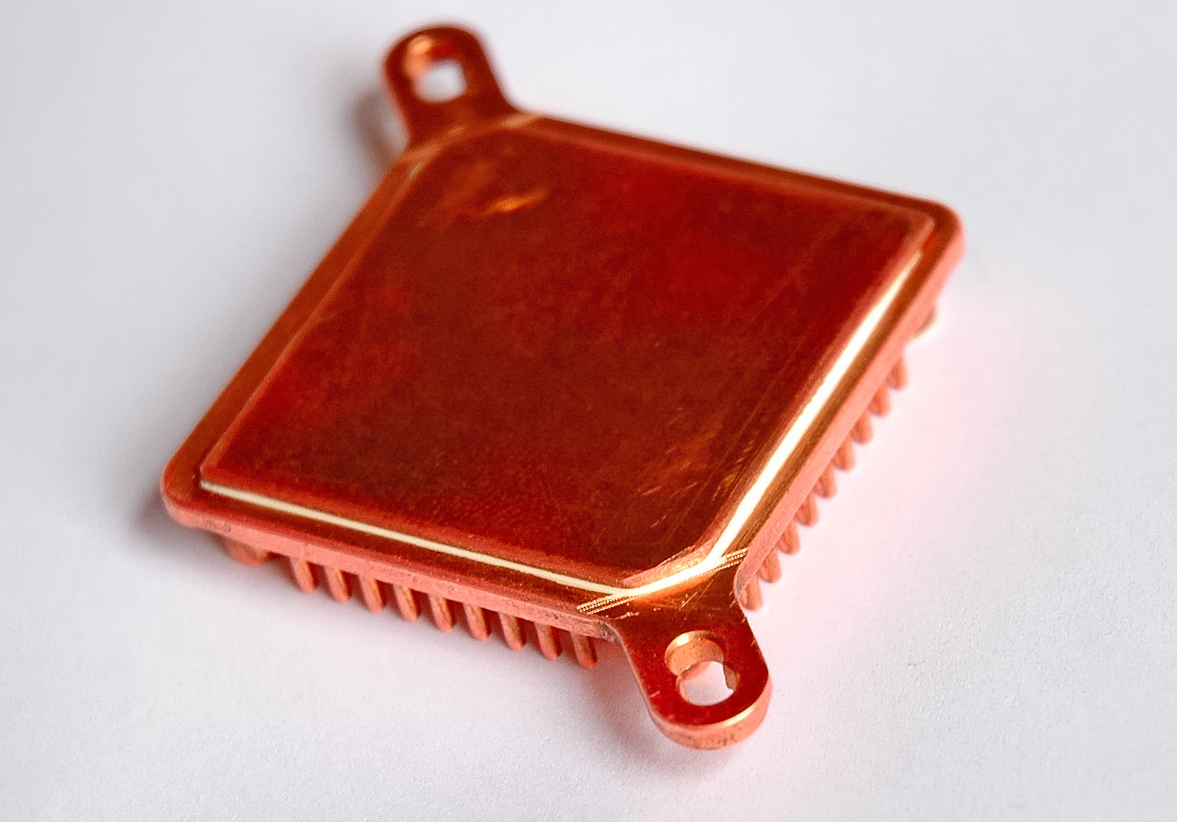
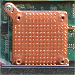
Mod the “North BridgeThermal Module Assy”. We will use two Copper DDR Heatsinks (remove any tapes) to extend the surface of the North Bridge Copper Pipe. To remove North BridgeThermal Module Assy take a look at "C90 Disassembly Procedure" on page 2-8, point 4. After removing use a tooth brush with tooth paste for cleaning of the Copper Pipe and two Copper DDR Heatsinks. Wash all with worm water and left them to dry.
Cleanse again very carefully the surfaces (pipe & two DDR heatsinks) with “Isopropyl Alcohol”. To stick heatsinks to the pipe use the thermal adhesive “Arctic Alumina Premium Ceramic Thermal Adhesive”. Follow the product directions and use “Spring Clamps”. At the end you have the next picture:
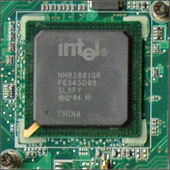
Change the thermal compound. “Cleaning! Cleaning! Cleaning!”. Use “Cotton Swabs” with “Isopropyl Alcohol” to clean the North Bridge crystal. Repeat the procedure in this way – use first wet (Isopropyl Alcohol) and immediately after that dry cotton swab to clean the crystal. Do the same for the “North BridgeThermal Module Assy”. Both of them must be extremely clean without a speck of dust, greasy spots, greasiness and residue. Don’t touch them with fingers! Here you are a picture of the North Bridge:
Put a drop of thermal compound on the “North Bridge Crystal” and mount the “North BridgeThermal Module Assy”.
That's it!
19. BIOS 1002A
The BIOS version 1002A supports Intel’s E7500 CPU (it’s a mod of original 1002). To update C90S with the last BIOS version 1002A follow the next steps:
1) Download BIOS “1002A” on .ISO image
2) Extract “C90S-Bios-ISO-1002A-1002.iso” file from the archive
3) Burn it on CD/DVD
4) Boot from the CD/DVD (press “ESC” key and choose “Boot from CD/DVD”)
5) Run “update.bat” (type without quotes at prompt and press “Enter”). It will start the Update Procedure for BIOS 1002AType on prompt:
A:\> update
Press “Enter”, BIOS will be updated with version 1002A.
This CD/DVD contain also and BIOS version 1002. If you want to update with 1002 just type on the prompt:
A:\> afudos /i1002.rom
6) Watch the screen. After the finish, restart your system
Now you have the last BIOS for C90S installed.
Bravo!
20. Upgrade CPU Intel E7500 ( Specifications )
Tip: Choose the right E7500
Before this important upgrade first you must to update your BIOS with version 1002A. “How to do that?”. Take a look at previous section “BIOS 1002A”.
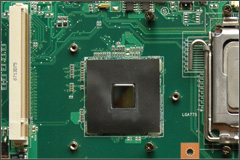
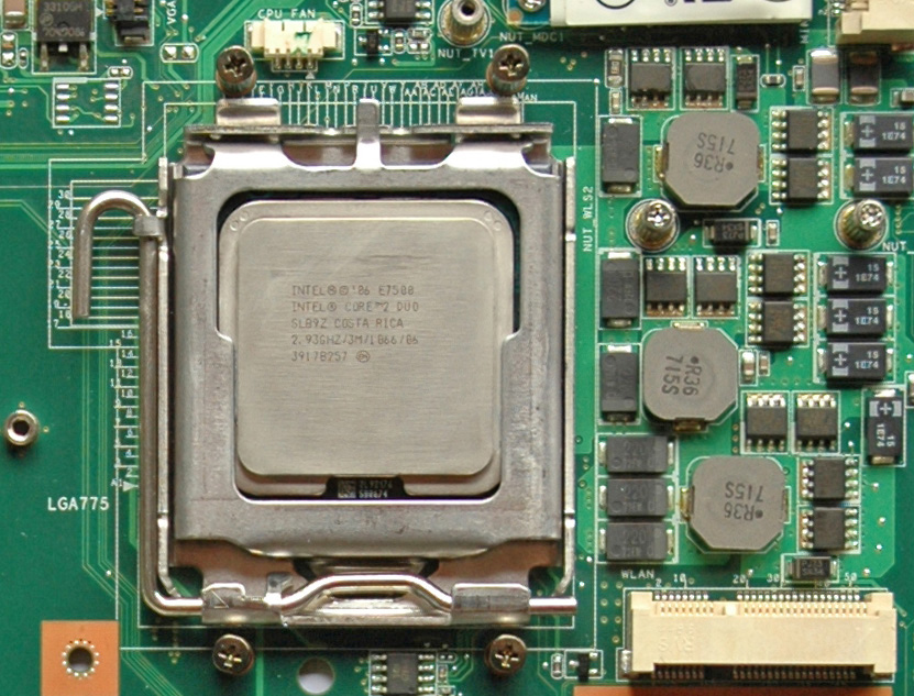
At the moment there are 3 different versions of E7500 Wolfdale with a real TDP ~ 100 Watts. Two of them support “Virtualization Technology” (VT-x) namely the revision SLGTE (Core Stepping R0/SLGTE). Make your choice and install the CPU. The procedure is simple and described in “C90 Disassembly Procedure” on pages 2-3 and 2-4. Here you are a picture on the CPU (Wolfdale SLB9Z that doesn't support VT-x) in C90S:
Use “Cotton Swabs” with “Isopropyl Alcohol” to clean the CPU and “CPU Thermal Module Assy”. Repeat the procedure in this way – use first wet (Isopropyl Alcohol) and immediately after that dry cotton swab to clean the CPU. Do the same for the “CPU Thermal Module Assy”. Both of them must be extremely clean without a speck of dust, greasy spots, greasiness and residue. Don’t touch them with fingers! Then use a thermal compound and mount the “CPU Thermal Module Assy”.
You have a cool & fast CPU for our C90S.
Thanks Intel!
21. WiFi Atheros AR9280 ( Specifications )
If you want to have a reliable wireless connection in any mode then Atheros AR9280 (802.11n/a/b/g 300 Mbps, 2Tx2R MIMO) is the choice. This is the best WiFi card for me. Fast with good range and support of all standards. We will follow the next steps:
1) Hardware Installation
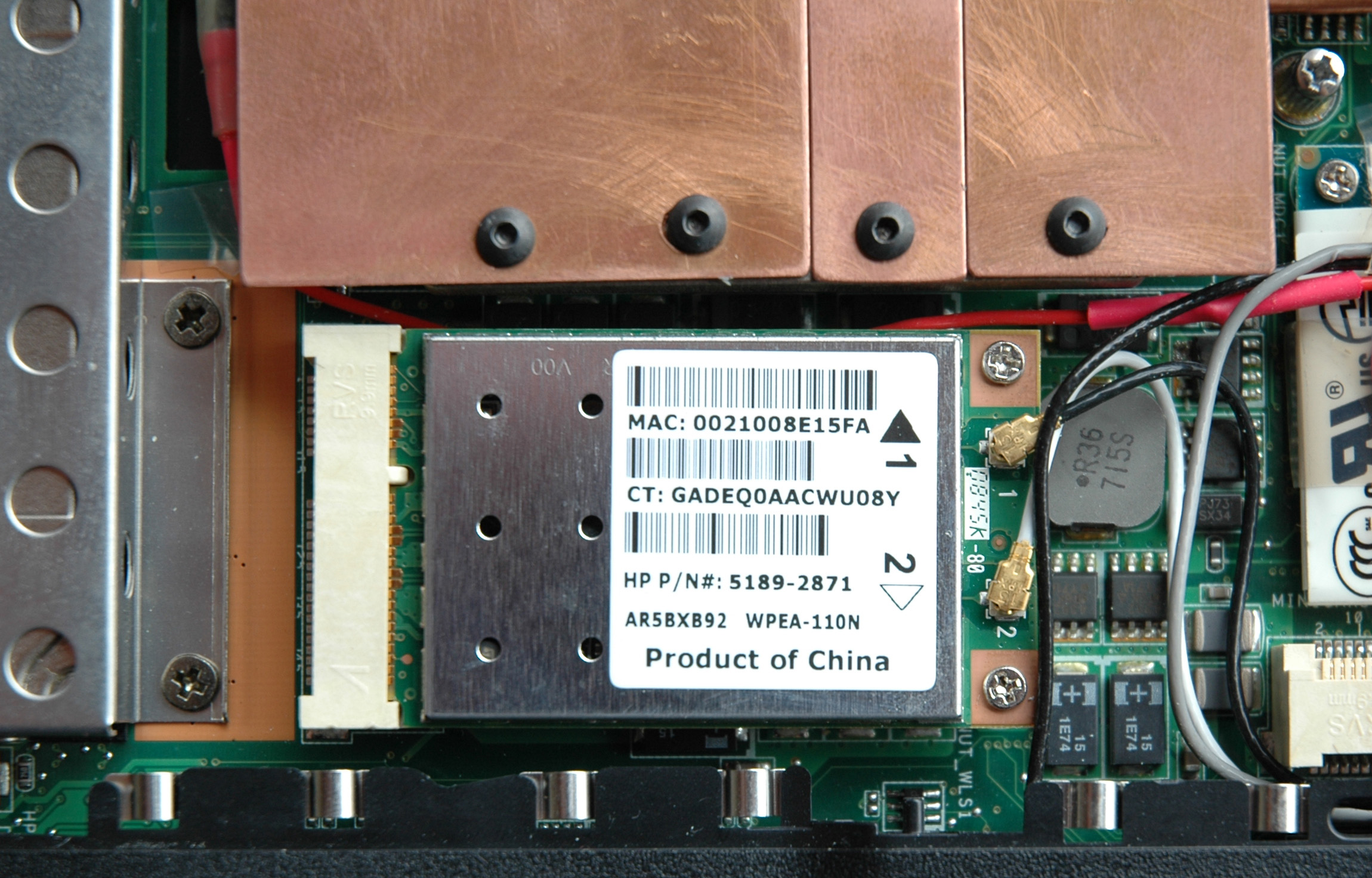
2) Driver InstallationHardware Installation. To install the WiFi card follow the procedure in “C90 Disassembly Procedure” on page 2-6. The Atheros card supports a two-antenna-wire design. The U.fl. connectors on the top edge of the card are labeled as 1 (black arrow) and 2 (white arrow). These indicate which antenna lead (white or black) is to be connected to which connector button. Connect the white and black cables to the antennas connectors as they are on the picture:
The third cable (the grey one) must be isulate and stick with a tape to the modem.
Driver Installation. Download the driver “Atheros WiFi AR9280 7.7.0.456 for XP ( 32&64-Bits )”. Extract the archive and go to the “Device Manager => Network Adapters”. Choose our WiFi adapter with a right mouse click and select “Update Driver …”, after that point extracted driver folder. Press OK and installation will start. After the finish restart the system and enjoy!
It’s little boring never to lose a connection and always having 300 MBits/s to any 801.11n router.
Thanks Atheros!
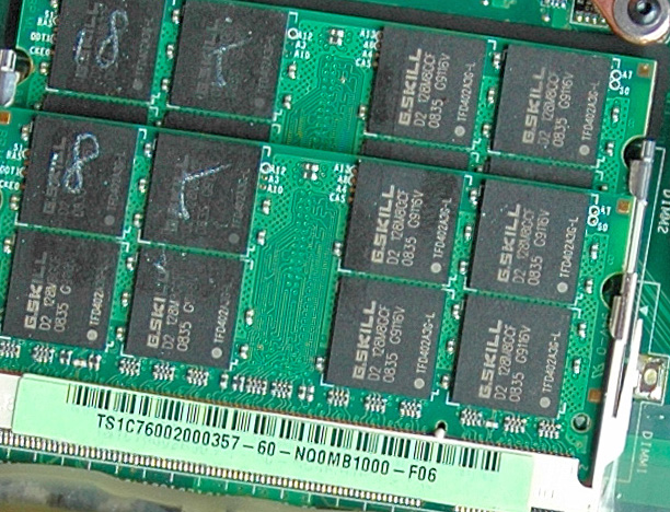
22. RAM G.SKILL F2-6400CL5D-4GBSQ
One of the most importing things is the RAM. When we have dual channel architecture as in C90S it's essential to have two identical DIMMs. That’s why we take the kit with two fastest 200-Pin DDR2 SO-DIMMs at 800MHz (PC2 6400) and timing 5-5-5-15. Except the speed another extra of this memory is a little bit of heat radiation. Here you are a picture:
It isn’t difficult to install the RAM. Follow the procedure in "C90 Disassembly Procedure" on page 2-4.
Thanks G.SKILL!
23. Fans & Airflows ( Specifications )
The cooling design is based on dynamic air flow. The fans in C90S are four good and powerful “Delta AFB0412VHB”. They cool two aluminum heatsinks attached to the three copper pipes – CPU, GPU and North Bridge. We have one fan for GPU & North Bridge and 3 fans for the CPU. Respectively they have different power sources and separate speed control. See the picture, white plug (CPU fans) and black plug (GPU fan):
A BIOS procedure(s) manages the fans according to different thermal conditions and CPU’s specifications. Fans management is not the same with different BIOS versions (“Why?”).
C90S has bad cooling design (it’s obvious), the source of all thermal problems. That’s why I designed “ASME”. If you follow my mods then required thermal policy for these mods perfectly much the thermal policy you already have in BIOS version 1002A (“Why?”).
Question: “Is that’s enough for the proper cooling?”
Answer: “YES! According to my thermal policy based on dynamic air flow the cooling is perfect!”Question: “Is there a better way to cool C90S?”
Answer: “YES, it is! From thermal point of view constant air flow is a better solution ("Why?").”C90S cooling based on constant air flow. We have a need from a constant power source. C90S is offering to us the next four possibilities for the case:
1) The Battery at constant 12.25V is not good decision as power source! I’m not recommending this approach! Something more it’s a wrong way! Don’t Do That!
2) The PSU or "Power Plug" near to the fan array at 19V is the right direction. I’m working on it and when I’m ready the solution will be here. Shortly, it’s a hardware implementation of a cooling solution based on constant air flow. It works only at 19V. When the power plug is “IN” we have the ability to switch between dynamic and constant cooling modes. Default state is dynamic. In a constant mode you can control fans voltage from 7V ~ 13V. In a case of missing AC power follows automatic switching to dynamic mode.
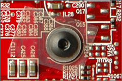
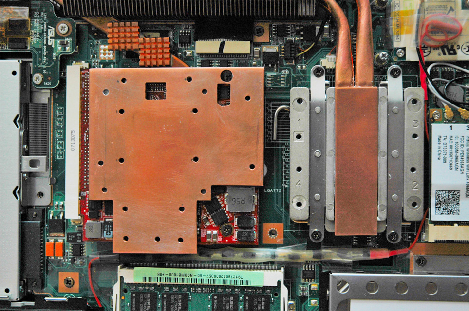
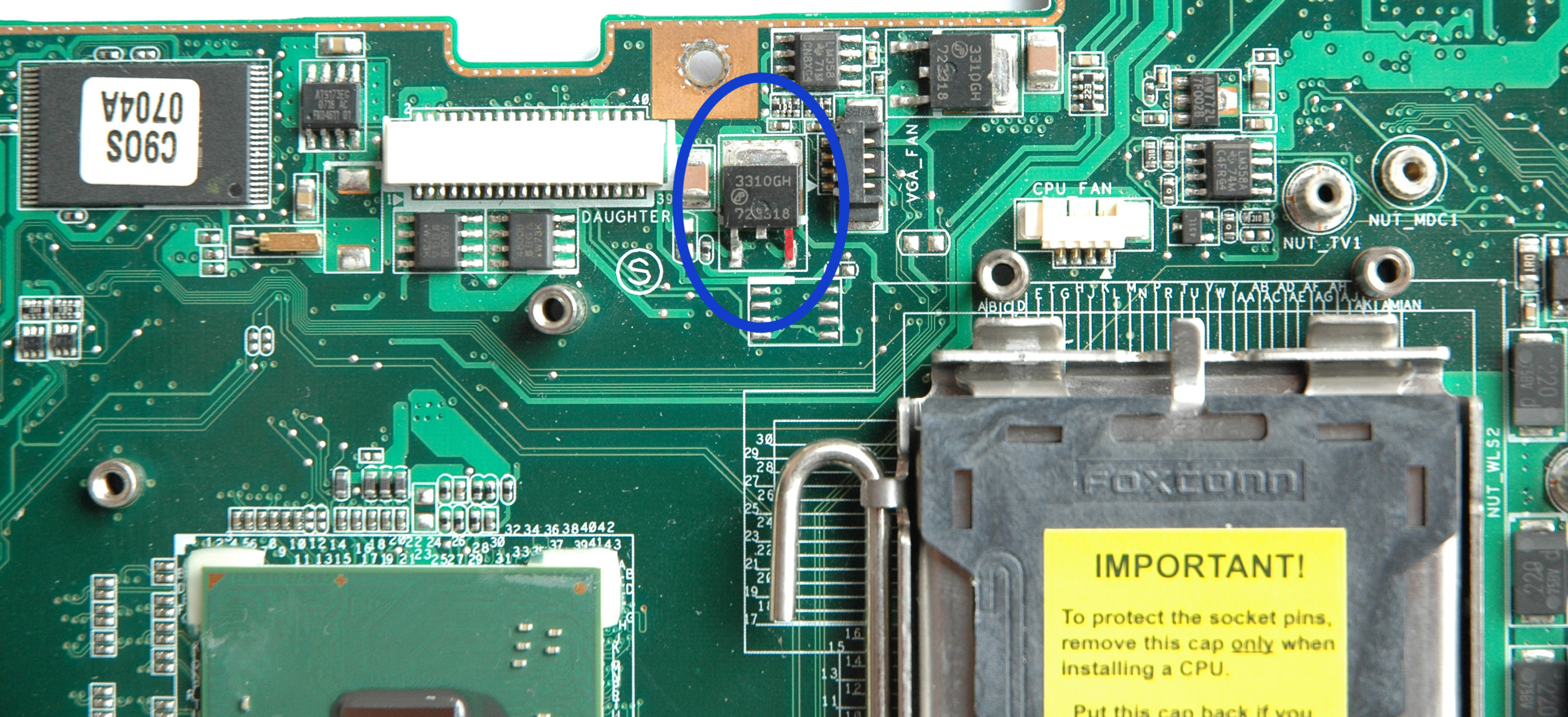
3) Constantly 12V from the right leg of the VR transistor 3310GH which is outlined in red on the picture:
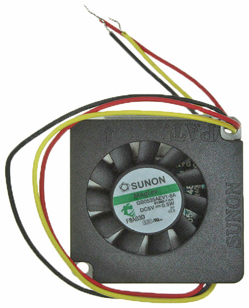
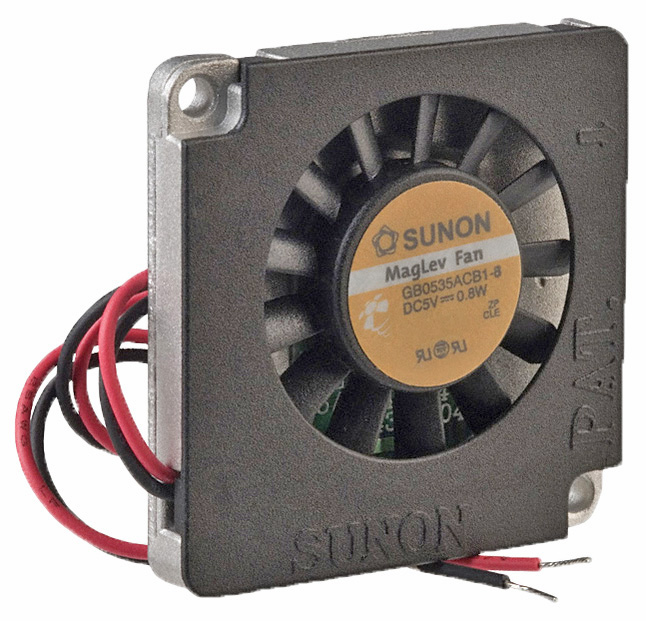
4) The motherboard revision 1.1G has system fan connector used to power a fan blower 40x40x6 mm at 5V attached to the South Bridge. Here you are pictures of the fan with 3 and 2 leads (for reference):
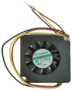
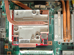
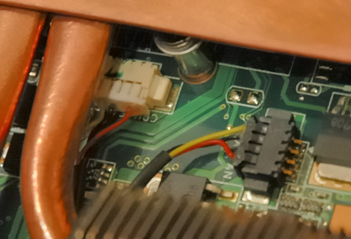
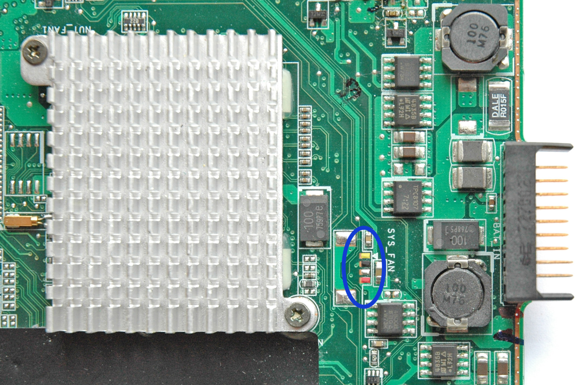
The layout of the motherboard makes useless the use of the fan at that place. That’s why it was replaced by the aluminum heatsink in the next motherboard revision 3.0G and the system fan connector was removed. The power interface assigned for the system fan is still available and can be used for 3 leads fan at 5V. Here you are the picture of the header location in colors:
CAUTION: Don’t solder anything to your motherboard! Without a clear vision and understanding you’ll destroy any system. At this point YOU are the biggest threat with such “smart thinking” for the C90S’s healthy.
“Two things are infinite: the universe and human stupidity and I'm not sure about the universe.”
Einstein
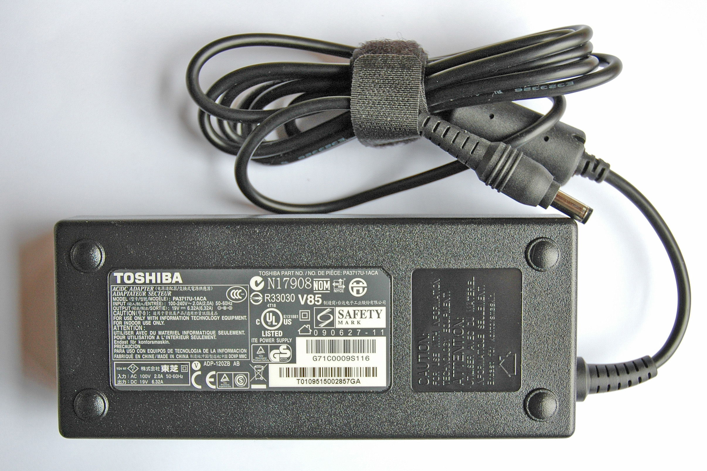
24. PSU Toshiba PA3717U-1ACA
PSU is one of the most important parts from our equipment. “Toshiba 120-Watt Global AC Adapter PA3717U-1ACA” is the best PSU for C90S. There isn’t a problem with the professional audio equipment. It runs cool and has long cables. Here you are a picture:
If you follow my way then your system will work also with the PSU “Toshiba 75-Watt Global AC Adapter PA3468U-1ACA”. There aren’t problems with any network interface and attached peripherals.
Thanks Toshiba!
25. Second HDD/SSD Drive Instead of the Optical Drive
This is possible thanks to the OBHD-SATA12-BU, a product of “NewMode Electronics”. The details are on their web site plus many interesting options.
Except the good quality, it works perfectly for me. The HDD temperatures in our second HDD compartment are lower between 5 ºC (ambient 30 ºC) and 7 ºC (ambient 20 ºC) than the original first one!
Thanks to this mod you’ll take the maximum from SSDs drives without to be sacrificed the reliability.
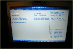
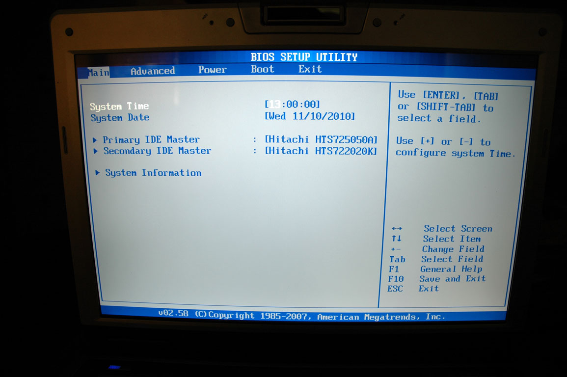
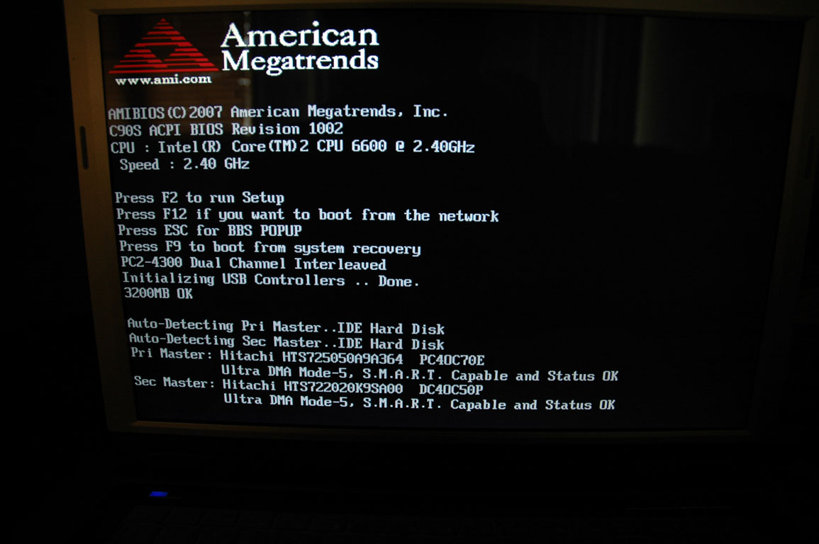
Here you are pictures of BIOS Setup & POST Screens:
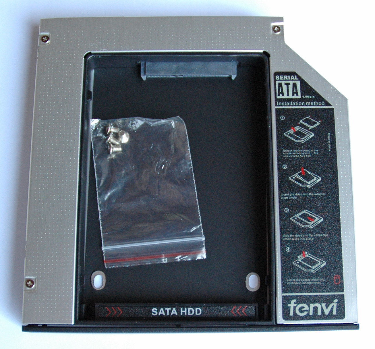
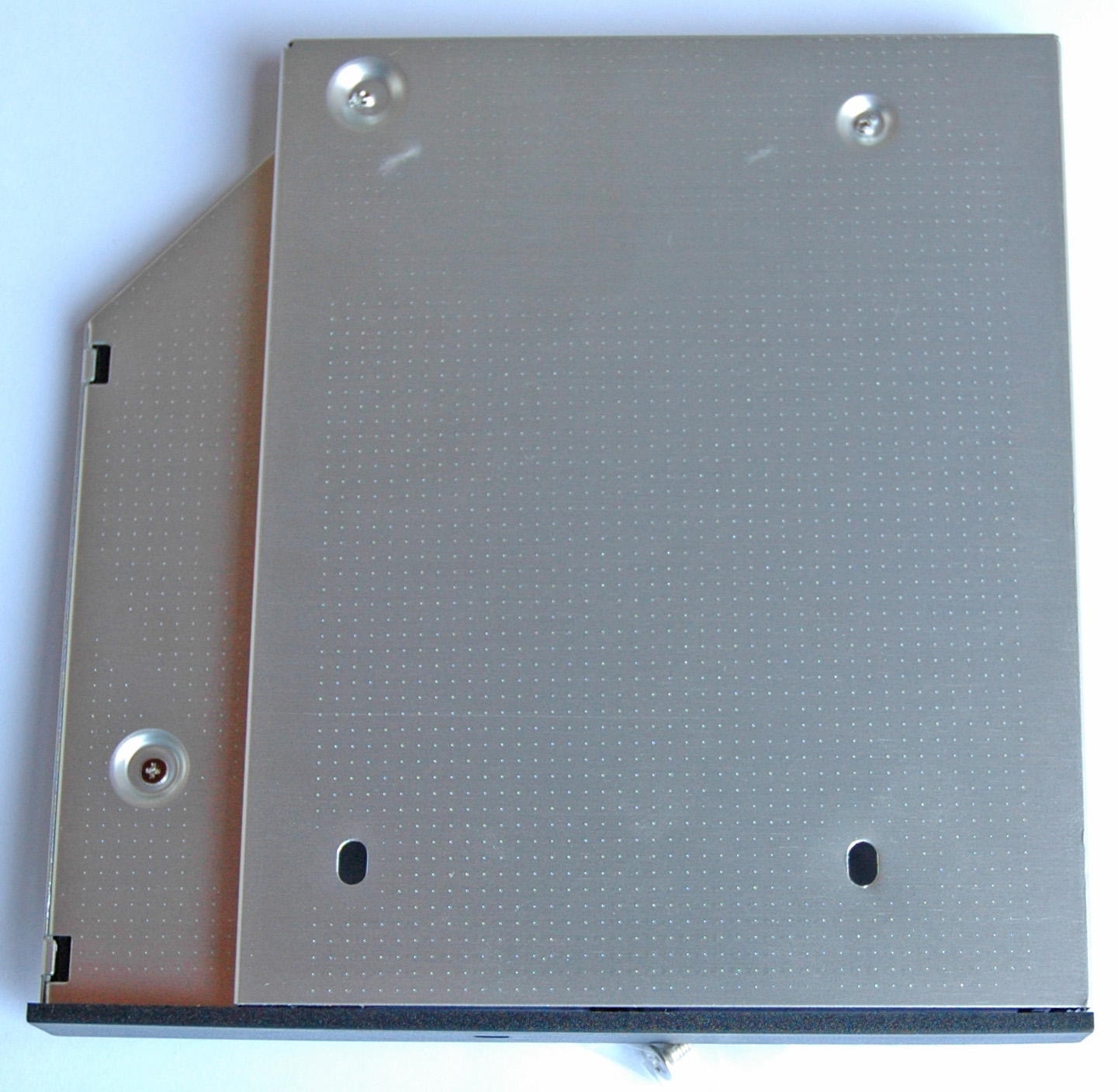
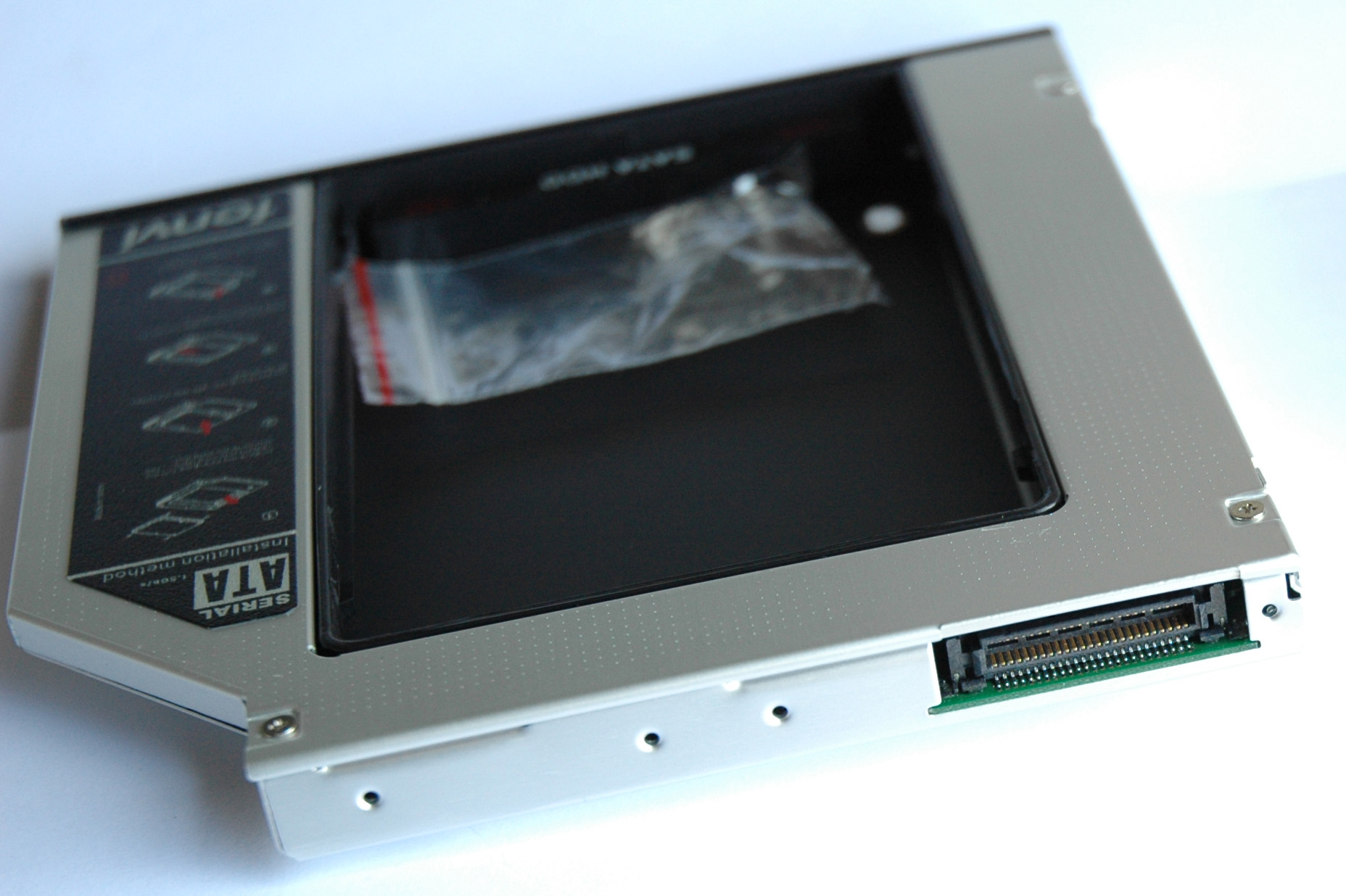
Here it is the alternative (10 US$) from another brand with its specifications and pictures:
- Optical Bay Hard Drive Caddy
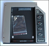
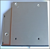
- External PATA interface
- Internal SATA interface
- Thickness 12.7 mm
26. TV Tuner and/or Second/Third SSD Drive
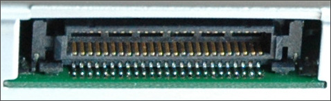
In our C90S we have two Mini PCI Express 1.0 slots. The first one holds the WiFi card while the second one is usually empty. It can be used for a TV card and that is cool because we have also and connector for an external TV antenna.
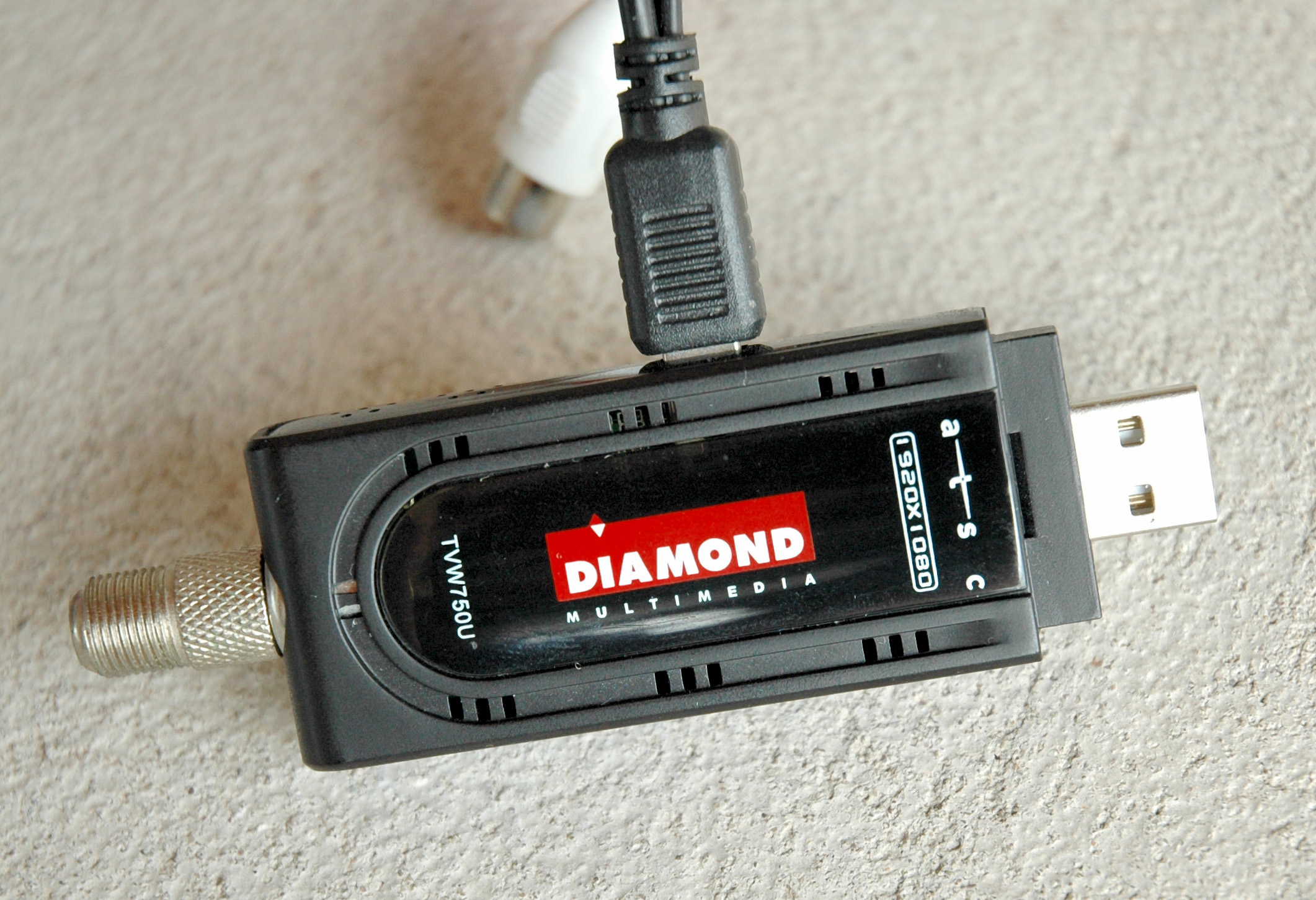
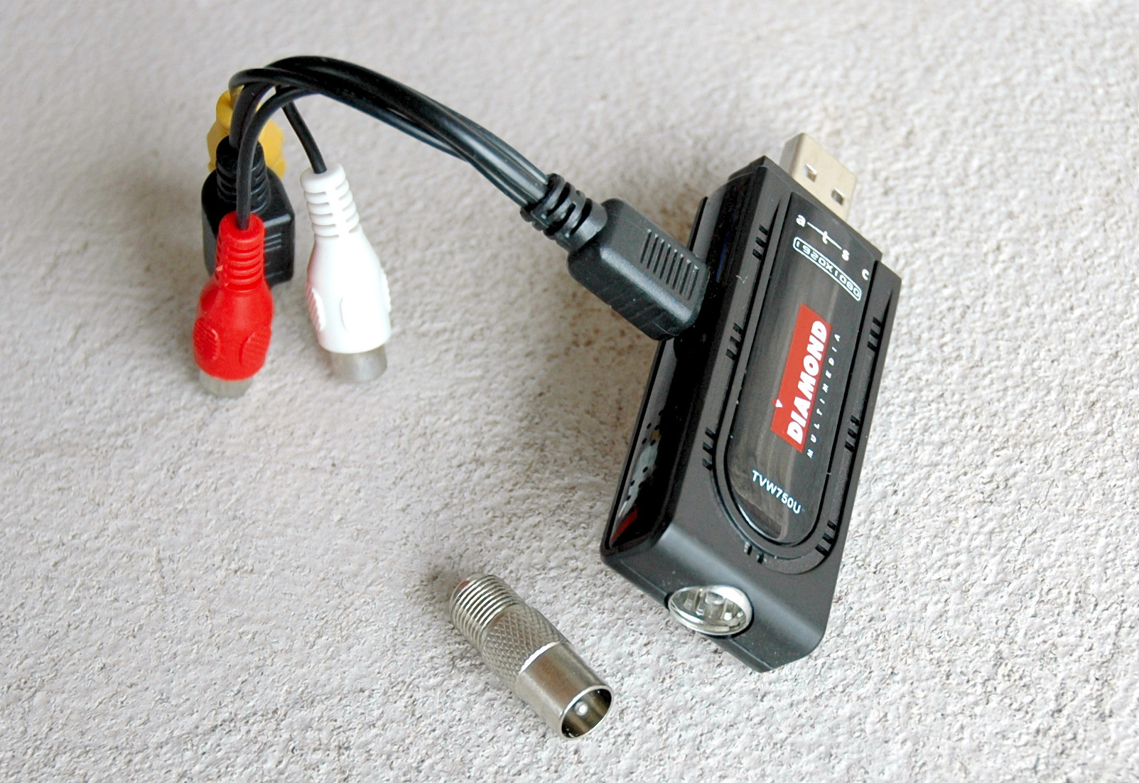
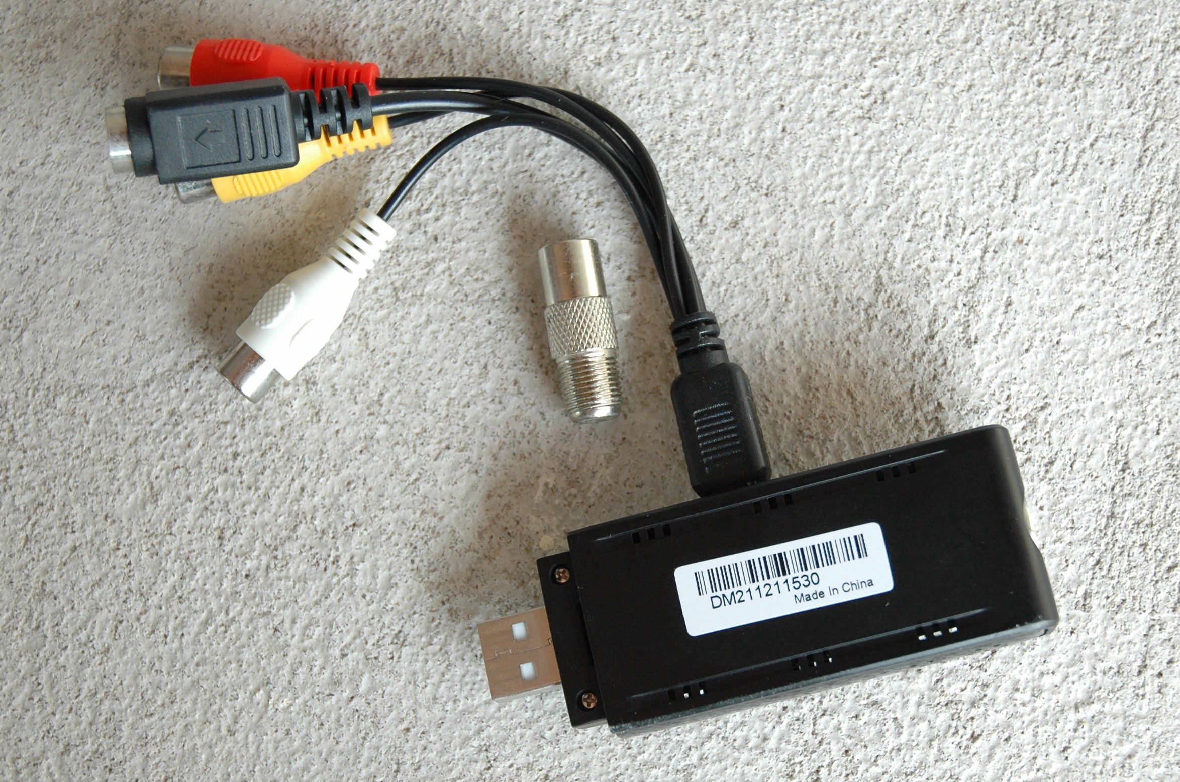
Personally I don’t like my second Mini PCIe interface to be wasted with a limited TV card. There is better solution from AMD namely “ATI TV Wonder HD750” with a USB interface. It works perfectly anywhere as an analog/digital/cable TV receiver and as a video capture. The Diamond was tested in US/HDTV & Europe/DVB-T/Analog as a TV tuner and everything was/is fine. The device capabilities as an analog video capture (NTSC/PAL) are fantastic - no freezes, no crashes or artifacts on the video and audio picture via Composite or S-Video inputs. I successfully digitized Betamax & MiniDV (Canon MV750i with not working digital interface) video tapes. Here you are pictures:
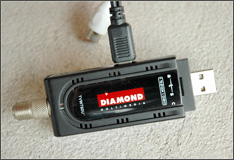
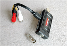
I conducted ~ 40 hours video session of heavy capturing at ~ 28 ºC (ambient) without any problem. The drivers are well written for the XP platform with SP3. The “ATI TV Wonder HD750” is a diamond and because I like diamonds I have Diamonds. Thanks AMD!
Well, back on the track with the precious empty Mini PCIe slot. The simple idea is just to plug in an SSD and … try to catch me. It sounds good, but there is a problem called mSATA - a different hardware protocol using the same socket like our old and good Mini PCIe. The fun starts here because most of the SSD on the market in form factor Mini PCIe use the mSATA interface or shortly don’t go. The solution is on its way to us …
The idea is the attached SSD drive with SATA interface to be controlled by the motherboard’s JMicron SATA controller. The max read speed will be around 100 MB/s and the max write one about 50 MB/s. I will post more data and details when the things are done.