10. Manuals
Manuals & Guides:
- C90S User’s Manual
- C90 Disassembly Procedure
- C90S Fans Specifications
- C90S Fans Embedded Controller
- ACPI Specification 4.0a
- C90S Chipset Mobile Intel 945 Express Datasheet
- C90S Chipset Intel 945 Express Family Datasheet
- C90S Chipset Intel 945 Express Family Specification Update
- C90S Chipset Intel 945 Express Family Thermal and Mechanical Design Guidelines
- C90P Chipset Intel P35 Express Chipset Product Brief
- C90P Chipset Intel P35 Express Chipset Thermal and Mechanical Design Guidelines
- How to apply Arctic Alumina Ceramic Thermal Adhesive
- How to use Thermal Compound
- How to Solder
- Surfacce Mount Soldering
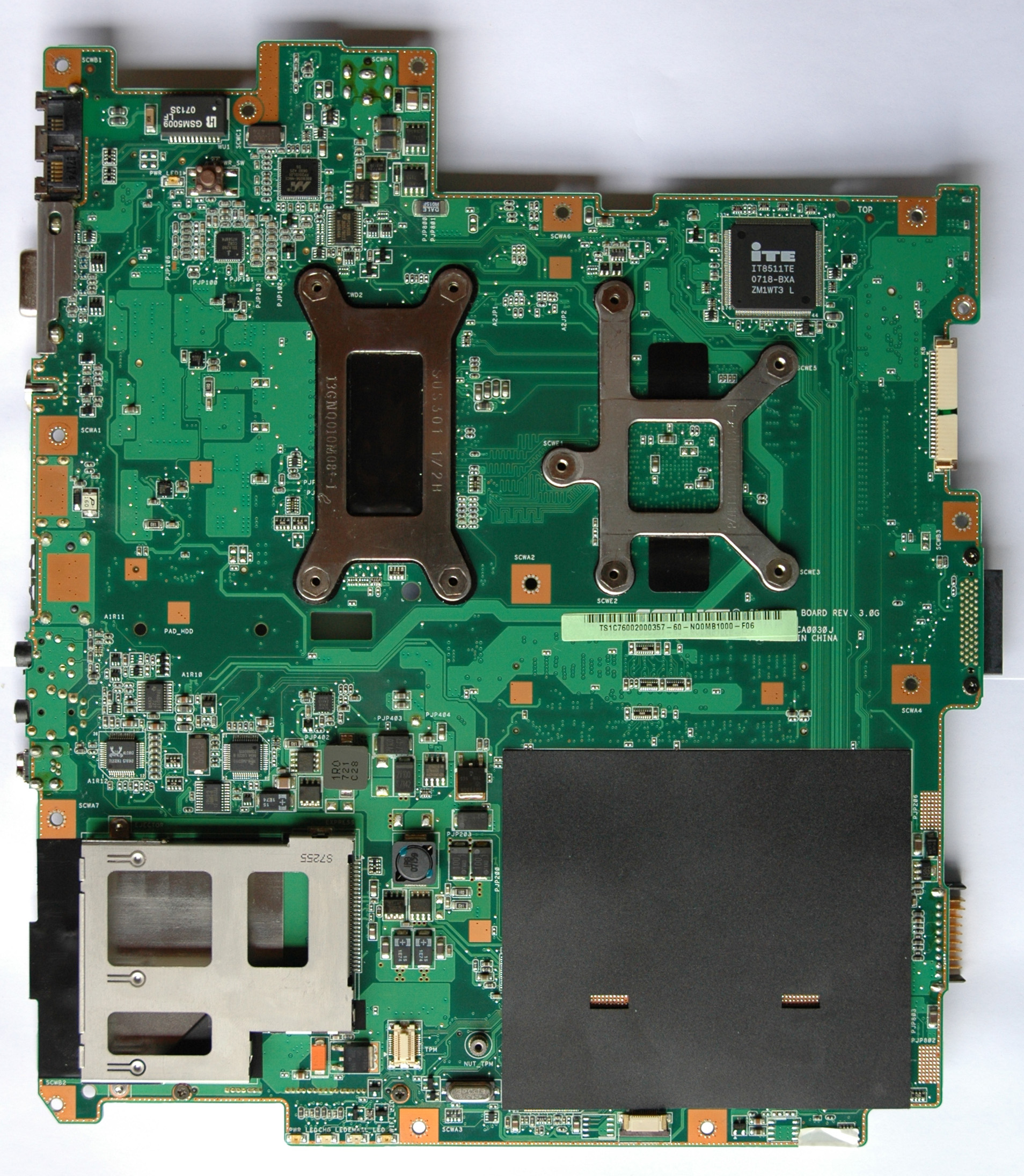
Motherboard Pictures:

11. Drafts ( Video Heatsink “ASME” )
Until now I’ve designed 9 revisions of the Video Heatsink “ASME”. Every new ASME version is based on the previous one plus extensions, additions and fine adjustments, e.g. the GPU heatsink from rev. 1.0 is the same one in rev. 2.0 & 3.0. The full technical documentation is provided only for rev. 1.0 and for the GPU heatsink in rev. 4.0.
The main difference between the two revisions is that in rev. 4.0 the strip between the GPU & CPU is only one with metric dimensions 152x76x0.8 and that the GPU heatsink has a smaller number of holes. From thermal point of view the difference is less than 1 ºC in favor of rev.1.0.
The rev. 4.0 is easy to be built and it’s the recommended way for you. Just for a reference - the best ASME rev. 9.0 keeps the temperatures with ~ 10 ºC lower than rev. 4.0 using the same thermal policy (the original C90S). It’s difficult for manufacturing and mounting.The quality of the drafts meets required standards on car industry and you can give them to any workshop from that industry (Renault, PSA, BMW, Honda, Ford, Chrysler …) without a technical explanation. The best way is to find out in your area some small workshop with CNC machines. Of course you can do it yourself in home environment as I did it.
Here you are the links with professional drafts in two scales – (Manufacturer/Workshop) & (Model/Template/Do It Yourself). Also you have and the 3D model. The heatsink is tested on ATI Mobility Radeon HD 3650/512/DDR2 & NVidia 9600M/GT/512/DDR3.
Drafts / Models / 3D Animated Model
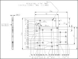
Manufacturer or Workshop
Drafts "ASME" 1.0Manufacturer or Workshop
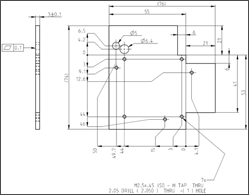
Draft "ASME" 4.0Do It Yourself
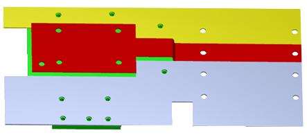
Models "ASME" 1.0
Do It Yourself
Model "ASME" 4.0
3D Animated Model "ASME" 1.0
- Heatsink Assembly 3D, Letter
- Heatsink Assembly 3D, A4
12. FAQ
Q) “Your drawings are ASME A4 and ISO? What is this world coming to?”
A) ASME is a standard which have nothing to do with "American Society of Mechanical Engineers". Tip: asus < ASME!
Q) “What are the considerations when bridging CPU and GPU heatsinks?”
A) Effective use of the CPU thermal assy.Q) “Did you have to resolder your heat pipe, or did you just grind off the aluminum?”
A) Just grind off the aluminum. Some of you make a mistake when are bending C90S heatpipes (they have a specific internal structure) because in that way you are reducing capacity of heat transfer.Q) “Does anyone know any places where I can buy plates of Copper?”
A) The best place for me in US is McMASTER-CARR. Here you are a link:Q) “What purpose do the extra holes you cut into your heat spreader serve?”
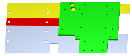
A) On the next picture is my VGA heatsink prototype which I’m using right now. All temperature results are with this one heatsink.
The distance between holes 1-2-3-4 is 41 mm.
“B” hole is ATI related. I used also this hole to read GDDR memory chip temperatures.
“C” hole was to put an external temperature sensor to measure GPU temperatures.Q) “Did you need spacers between the heatspreader and the card, … ?”
A) Yes. Spacers (Aluminum) Height: 1.70 mm. (ATI Mobility Radeon HD 3650 512MB DDR2). NVidia 9600M GT 512M DDR3 spacers are higher than ATI’s (Height: 2.28 ~ 2.30 mm.).Q) “I have some questions related to your mode. Let me know where to find you.”
A) I’ll be glad to answer at all your questions. If you prefer you can use my e-mail ( Angel.Marinov@sineva.net ) with mail’s subject that contain “C90S:”.Q) “Did you happen to have to do any vBIOS mods for your HD 3650?”
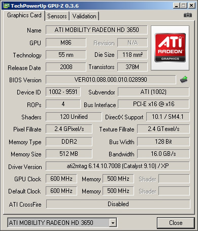
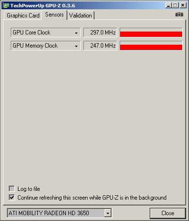
A) No, I’m not. Just plug & play. Here you are GPU-Z info from my ATI Mobility Radeon HD 3650 with 512MB DDR2.Graphics Card & Sensors:
Q) “I've decided to buy a 3650 and some copper to start working on it but I can’t find the thermal padding used in the original post. Do I really need it?”
A) No, in the context of “ATI Mobility Radeon HD 3650 with 512MB DDR2”. My personal suggestion to you is to use (made by you) copper’s pads (14.5 x 11 x 0.8~0.78mm) as I do on the next picture:
Q) Can someone link me where I can get some good thermal padding if its really needed? Also about the aluminum spacer used on the mod, where can I get one as well?
A) In the US all you need is on:Q) “ … what did you use for the heatsink backplate on your HD 3650 Angel?”
A) Nothing! The use of a backplate is a bad decision. The idea to attach a video heatsink in that way is unique. Here you are the picture you need:
Q) Where did you get those threaded screw mount things?
A) At www.mcmaster.comPicture of Video Adapter Screw M2.5 x 6:
The 3D Model of the screw ( pdf, 469kb )
Q) “As for fastening the heatsink to the card to you just use a simple threaded bolt or what?”
A) The answer is in front of your eyes. Please look at the picture carefully:
Q) “If you could give me the exact links to both the exact screw model and bolt you used …”
A) Here you are the links to the screw (M2.5 x 6 mm) and tools you needed to make the holes:Socket Cap Screw M2.5 x 6 mm:
Q) “… could you tell the score of hd3650 in 3dmark05/06, …”
A) The 3DMark’06’s score of “ATI Mobility Radeon HD 3650 512MB DDR2” is 3623.
Q) “Related to cooper pads, is it the height distance between the GPU and MEM chips only 0.8mm?”
A) I can’t measure exactly that clearance.I have two “ATI Mobility Radeon HD 3650 512MB DDR2” and the thickness of copper’s memory pads is different for every one of them. The reason for that is called tolerance. Every component (PCB, GPU, Memory chips. heatsink) and process (wave solder process, our actions) they have its own tolerances. That’s why I used for memory pads two copper’s sheets with thicknesses 1/32” (0.79375 mm) and 0.032” (0.8128 mm). In my case I filed 0.005 mm ~ 0.010 mm. Then I used thermal compound Noctua NT-H1 from both sides of the pads. Most manufactures use regular thermal pads because it’s fast and easy way to deal with the tolerances.
Q) “I think there is still a small clearance between the pads and the RAM and Heatsink. Can this < .5 mm space be gapped by thermal compound on both sides?”
A) Yes, you can do that. In my opinion 0.5 mm is still big clearance. My suggestion is to check it in this way:1) Put a drop of thermal compound on all 4 memory chips.
2) Firmly press copper’s memory pads over the chips.
3) Attach the heatsink to the video card.
4) With a tooth stick try to push every pad gently. If someone of them slips freely then you needed more thickness.Some compounds are dangerous if you are not careful (e.g. Arctic Silver 5 – slight electrical conductivity).
Q) “I got 2mm THK Nylon spacers. How did you get 1.7mm spacers? by filing them down?”
A) Yes! I used a diamond file for that job. Here you are my file and spacers:
Metric Aluminum Unthreaded Round Spacer, 6mm Od, 2mm Length, M3
Standard Diamond Hand File, Flat, Medium (120) Grit, 0.25" Width
Q) “I've been talking to a CNC place in my area, and they're asking about square corners vs having a minimum radius?”
A) 1 mm ~ 1.25 mm. Give them the WEB site link of “C90S Unleashed” too and the freedom to choose that what they can do according to its equipment and abilities. Listen them very carefully, they are experienced professionals.Don’t forget to check “ASME” model ([Models / Do It Yourself] & [Video Heatsink “ASME”]) with your VGA & C90S before to order.
Q) “I find copper 0.9mm thickness instead of 0.8mm. May I buy it, will it fit as well?”
A) It’s OK to use thickness 0.9 mm instead of 0.8 mm.Q) “What is the tolerance for the video heatsink thickness?”
A) It’s between 2.5 mm and 3.2 mm. Here it is the current thickness of the Video Heatsink “ASME” prototype:
Actually the video heatsink with 2.5 mm thickness will be better than 3.2 mm. I am using 3 mm ~ 3.2 mm because there is additional mod which wasn’t described yet. The reason is the requirement of quality industrial equipment for that mod. The temperatures are with 3 ºC lower against the original “ASME” 1.0 / 4.0.
Q) “I have found a company who will make the ASME heatsink. They can’t make the tolerance to +/- 0.1 but can ask if it could be relaxed to +/- 0.2?”
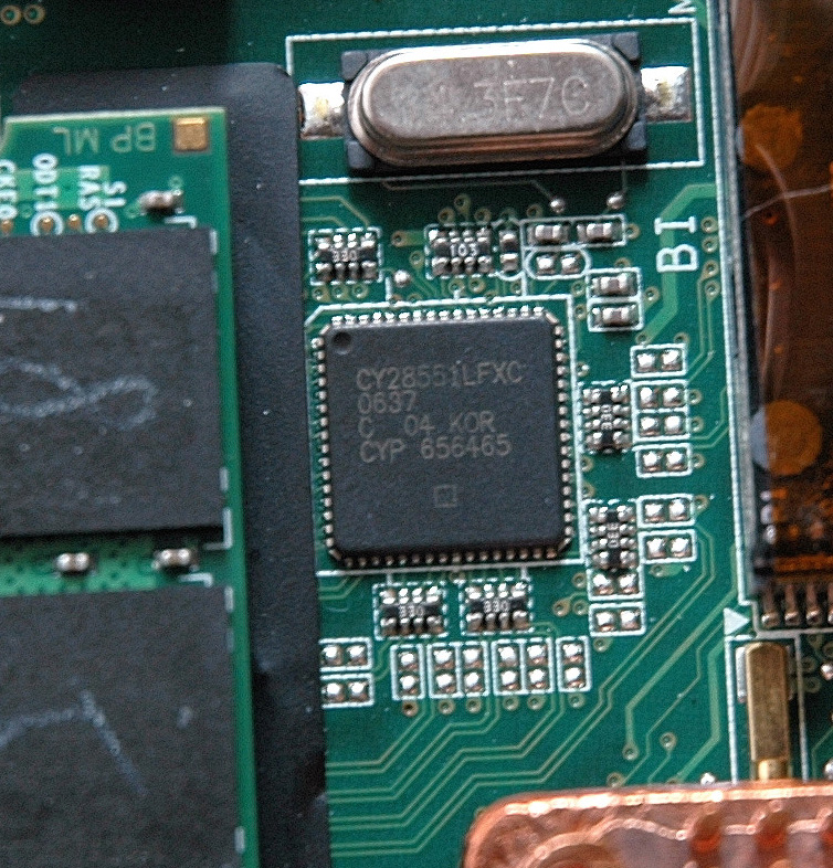
A) Yes, it’s OK to use a tolerance +/- 0.2 mm.Q) “What is the model of PLL chip?”
A) It's "Cypress CY28551LFXC". Here you are a picture with the chip:


13. Links (Theory & Practice)
Thermal Design & Cooling
Basic Theory
Notebook Design Considerations
Technologies Used - Notebooks
Advanced Cooling for Power Electronics
Advanced Cooling Methods for High Power Density in Electronic
Blister Liquid Cold Plates Analysis
Board Level Thermal Analysis via Large Eddy Simulation Tool
Bonding and Brazing Technologies for Power Electronic Cooling
Closed Loop Liquid Cooling for High Performance Computer Systems
Computational Method for Characterization of a Microchannel Heat Sink Involving Two-Phase Flow
Cooling to keep your Key Chips Alive
Effect of Obstruction Near Fan Inlet on Fan Heat Sink Performance
Flat Plate Evaporator for Electronic Cooling
How to Select a Heatsink
Loop Heat Pipe Technology for Cooling Computer Servers
Surface Mount Technology Cooling for High Volumes Applications
Testing the Thermal Resistance and Power Capacity of Production Heat Pipes
The Thermal Resistance of Pin Fin Heat Sinks in Transverse Flow
Thermal Performance Modeling and Measurements of Localized Water Cooled Cold Plate
Thermal Performance of an Elliptical Pin Fin Heat Sink
Thermal Performance of Interface Material in Microelectronics Packaging ApplicationsQuestions & Answers
What are the basic concepts about thermal design of using semiconductor devices?
What type of modeling is thermal design based on?
Where does thermal resistance occur?
What is the relationship between the junction temperature and the thermal resistance?
Could you show some cases of thermal design?
What size heat sink is necessary?
Why is the thermal resistance of the package not prescribed for some ICs?Heat Conduction & Transfer
Heat Transfer Equations
Conductive Heat Transfer
Heat Transfer
General Conduction Theory in Heat TransferHeat Load & Capacity Calculations
Calculating the Size of a Server Room Air Conditioner
Heat Capacity Calculations
Heat Load Calculations – Heat Gain for Air Conditioner SizingThermal Conductivity
Thermal Conductivity and the Wiedemann-Franz Law
Thermal Conductivity
Thermal Properties of Metals
Thermal Conductivity of Some Common MaterialsHeatsink Design
The Design of Heatsinks
Cryo Tech and New Cooling Technologies You Have Never SeenHeat Pipes
What's a Heat Pipe?
What is Heat Pipe?
Heat Pipe Assemblies Design Guidelines
How a Heat Pipe Works
Heat Pipe Basics
Benchtest - Heat Pipe
Heat pipe, heat pipe structure and principle
Laptop Heat Pipe
SEKI HEAT PIPE - Seki Hightech Co., Ltd.
Making a heat pipe by Doug KalmerPeltier
FAQ & Technical Information
Thermoelectric Cooler Modules
Peltier Thermoelectric Device Information Directory
The Heatsink Guide - Peltier Cooler Information
QKits Electronic Kits: QK66, 6A Peltier Thermo Electric Module
Standard TEC's : Sorted by Imax
TEC MountingBasic Knowledge in Electronics
Basic knowlege of Electronic Parts
Video Lectures
Diodes 1
Diodes 2
Diodes 3
How to Use Zener DiodesElectronics Stores
Fans
Computer Cooling Fans AC Axial Fan
Mouser
Newark
NMB
Future Electronics
Sunon Products
Fans & Fan Controllers
BuyExtras - 50 x 50 x 10mm USB Fan
MULTICOMP - DC MINI BLOWER, 30 X 3MM, 5V
ThermalFX - CSC-405AP 5 Volt Chipset Cooler
Sunon DC Brushless Fans & Blowers
Sunon DC Mighty Mini-Fans & BlowersFan Speed Control
Why and How to Control Fan Speed for Cooling Electronic Equipment
How PC Fans Work
How Brushless DC Motors Work
The Hall Sensor
555 Theory
A Little About Fans & Fan Speed Control
Dr. Calculus Technical Calculators
Integrated Circuits
Basic Transistor Circuits
PWM Modulation
Reducing Fan Speeds
How to Control Motor Speed with a PWM Circuit
Adding Fan Speed Control
Voltage Regulators Rev Up PWM-Based Fan Control
PWM Fan controller
PIC 3-Wire Fan RPM Controller
Linear DC Motor Speed Controller Using a Simple PWM Switching Mode Power Supply
On-Off Temperature Control
Coolerguys Programmable Thermal Fan Controller with LED Display
Build Yourself a Fan Temperature Control by Tillmann SteinbrecherFan Speed Embedded Controllers & Documentations
Embedded Controller IT8511E/TE/G (Preliminary Specification version 0.4.1)
ACPI Specification 4.0aFan Speed Applications
NoteBook FanControl by Stefan Hirschmann (needs a proper thermal policy configuration file for C90S)
Temperature Controller
Thermal Materials
Silver Sheets : Surepure Chemetals, 99.95% Pure Silver
Insulation : Kapton Tapes, 1 Mil Kapton Tape
Double Sided Thermal Tape : Bond-Ply 100 (5 mil) : Sekisui #5760
Arctic Alumina Thermal Adhesive
Heatshrink
Heatsinks & CoolingSoldering
How and WHY to Solder Correctly by Curious Inventor
Surface Mount Soldering 101 by Curious Inventor
SMD Soldering Guide by Infidigm
Solder Joint and Chip Resistor Integrity Issues for Large Case Size ChipsBIOS Recovery
Manufactures
WEB Site Dedicated to C90S:
My spirit and motivation comes from human wisdom, art, music, poetry, literature and knowledge. My Philosophy is here, in the books:
Question: “Who made the first trip to the Moon?”